
Radio Control Giants
Sal Calvagna <[email protected]>
Reduce vibration to make your gas-powered models last longer
GASOLINE two-stroke engines power most Giant Scale models. Fuel efficiency by glow-fuel standards and extreme reliability are two of their positive attributes, but one of their greatest negative attributes is vibration.
Some may disagree since weight and size are also concerns for modelers; however, newer gas engines that are more compact, lighter in weight, and closely resemble their glow-fuel counterparts are being designed. Ignition modules have replaced many heavy parts such as coils and flywheels.
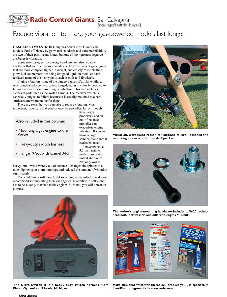
Engine vibration is one of the biggest causes of airplane failure. Anything bolted, screwed, glued, hinged, etc., is eventually doomed to failure because of excessive engine vibration. This also includes electrical parts such as the switch harness. The receiver switch is especially subject to failure because it is usually mounted to a hard surface somewhere on the fuselage.
There are steps you can take to reduce vibration. Most important, make sure that you balance the propeller. Larger models have larger propellers, and an out-of-balance propeller can exacerbate engine vibration. If you are using a large spinner, make sure it is also balanced. I once owned a 3.5-inch spinner made from cast or milled aluminum. Not only was it heavy, but it was severely out of balance. I changed the spinner to a much lighter spun-aluminum type and reduced the amount of vibration significantly.
You could use a soft mount, but some engine manufacturers do not recommend soft mounting their gas engines. In addition, a soft mount has to be suitably matched to the engine; if it is not, you will defeat its purpose.
Also included in this column:
- Mounting a gas engine to the firewall
- Heavy-duty switch harness
- Hangar 9 Sopwith Camel ARF
The photograph of a Piper L-4 shows what engine vibration can do to a gas-powered model. During a flight, trim and throttle problems became apparent. As the flight continued, these problems became severe to the point where the throttle stopped working at slightly less than half power. More than 20 minutes later the model finally ran out of gas and landed successfully. The source of the problem quickly became apparent: the engine bolts had backed out because of engine vibration and the fiberglass cowling was the only support holding the engine in place. The outcome could have been tragic, but only the cowl needed to be repaired or replaced.
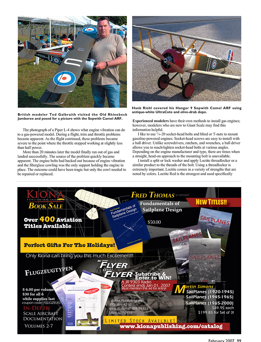
Experienced modelers have their own methods to install gas engines; however, modelers who are new to Giant Scale may find this information helpful. I like to use 1/4-20 socket-head bolts and blind or T-nuts to mount gasoline-powered engines. Socket-head screws are easy to install with a ball driver. Unlike screwdrivers, ratchets, and wrenches, a ball driver allows you to reach and tighten socket-head bolts at various angles. Depending on the engine manufacturer and type, there are times when a straight, head-on approach to the mounting bolt is unavailable.
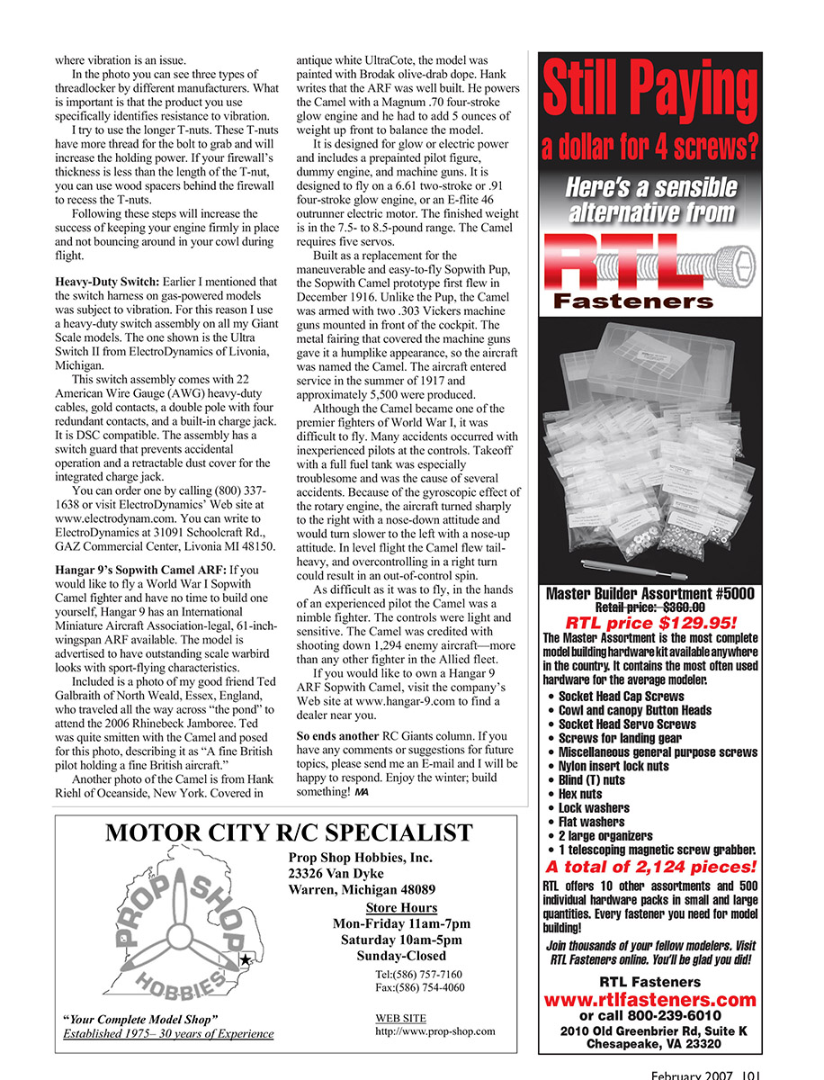
I install a split or lock washer and apply Loctite threadlocker (or a similar product) to the threads of the bolt. Using a threadlocker is extremely important. Loctite comes in a variety of strengths that are noted by color; Loctite Red is the strongest and is used specifically where vibration is an issue.
I try to use the longer T-nuts. These T-nuts have more thread for the bolt to grab and will increase the holding power. If your firewall's thickness is less than the length of the T-nut, you can use spacers behind the firewall to recess the T-nuts. Following these steps will increase the likelihood that your engine remains firmly in place and not bouncing around in your cowl during flight.
Heavy-Duty Switch
Earlier I mentioned that the switch harness on gas-powered models is subject to vibration. For this reason I use a heavy-duty switch assembly on all my Giant Scale models. The one shown is the Ultra Switch II from ElectroDynamics of Livonia, Michigan.
This switch assembly comes with 22 American Wire Gauge (AWG) heavy-duty cables, gold contacts, a double pole with four redundant contacts, and a built-in charge jack. It is DSC compatible. The assembly has a switch guard that prevents accidental operation and a retractable dust cover for the integrated charge jack.
You can order one by calling (800) 337-1638 or visit ElectroDynamics' website at www.electrodynamics.com. You can write to ElectroDynamics at 31091 Schoolcraft Rd., GAZ Commercial Center, Livonia, MI 48150.
Hangar 9's Sopwith Camel ARF
If you would like to fly a World War I Sopwith Camel fighter and have no time to build one yourself, Hangar 9 has an International Miniature Aircraft Association–legal, 61-inch wingspan ARF available. The model is advertised to have outstanding scale warbird looks with sport-flying characteristics.
Included is a photo of my good friend Ted Galbraith of North Weald, Essex, England, who traveled all the way across the pond to attend the 2006 Rhinebeck Jamboree. Ted was quite smitten with the Camel and posed for this photo, describing it as "A fine British pilot holding a fine British aircraft."
Another photo of the Camel is from Hank Riehl of Oceanside, New York. Covered in antique white UltraCote, the model was painted with Brodak olive-drab dope. Hank writes that the ARF was well built. He powers the Camel with a Magnum .70 four-stroke glow engine and had to add 5 ounces of weight up front to balance the model.
The Camel is designed for glow or electric power and includes a prepainted pilot figure, dummy engine, and machine guns. It is designed to fly on a .61 two-stroke or .91 four-stroke glow engine, or an E-flite 46 outrunner electric motor. The finished weight is in the 7.5- to 8.5-pound range. The Camel requires five servos.
Built as a replacement for the maneuverable and easy-to-fly Sopwith Pup, the Sopwith Camel prototype first flew in December 1916. Unlike the Pup, the Camel was armed with two .303 Vickers machine guns mounted in front of the cockpit. The metal fairing that covered the machine guns gave it a hump-like appearance, so the aircraft was named the Camel. The aircraft entered service in the summer of 1917 and approximately 5,500 were produced.
Although the Camel became one of the premier fighters of World War I, it was difficult to fly. Many accidents occurred with inexperienced pilots at the controls. Takeoff with a full fuel tank was especially troublesome and was the cause of several accidents. Because of the gyroscopic effect of the rotary engine, the aircraft turned sharply to the right with a nose-down attitude and would turn slower to the left with a nose-up attitude. In level flight the Camel flew tail-heavy, and overcontrolling in a right turn could result in an out-of-control spin.
As difficult as it was to fly, in the hands of an experienced pilot the Camel was a nimble fighter. The controls were light and sensitive. The Camel was credited with shooting down 1,294 enemy aircraft—more than any other fighter in the Allied fleet.
If you would like to own a Hangar 9 ARF Sopwith Camel, visit the company's website at www.hangar-9.com to find a dealer near you.
So ends another RC Giants column. If you have any comments, suggestions, or future topics, please send me an email and I will be happy to respond. Enjoy the winter; build something!
Transcribed from original scans by AI. Minor OCR errors may remain.

