
Radio Control Giants
Sal Calvagna [[email protected]]
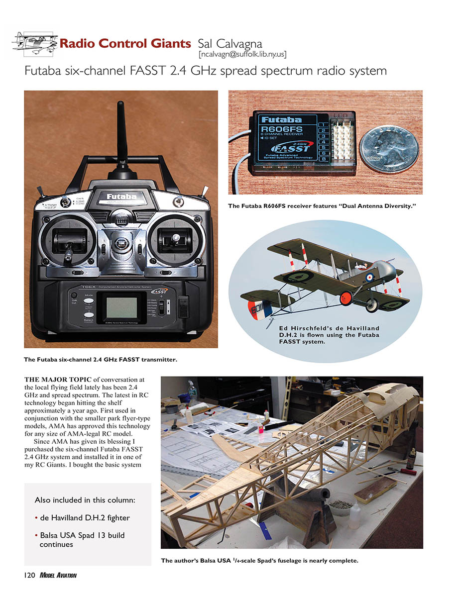
Futaba six-channel FASST 2.4 GHz spread spectrum radio system
The major topic of conversation at the local flying field lately has been 2.4 GHz and spread spectrum. The latest in RC technology began hitting shelves about a year ago. First used with smaller park-flyer models, the AMA has approved this technology for any size of AMA-legal RC model.
Since AMA gave its blessing, I purchased the six-channel Futaba FASST 2.4 GHz system and installed it in one of my RC Giants. I bought the basic system that includes the transmitter, receiver, charger, and switch harness.
A few immediately noticeable differences from traditional 72 MHz radio systems:
- The transmitter antenna is extremely short — quite a departure from the telescoping antenna on 72 MHz systems.
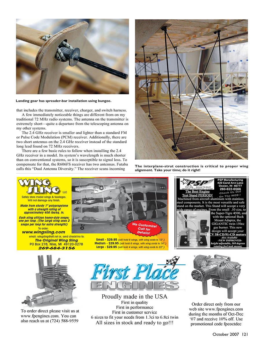
- The 2.4 GHz receiver is smaller and lighter than a standard FM or PCM receiver.
- The receiver has two short antennas instead of the single long lead found on 72 MHz receivers.
Basic rules and installation considerations for the 2.4 GHz receiver:
- The system’s wavelength is much shorter than conventional systems and is therefore more susceptible to signal loss.
- The R606FS receiver uses two antennas in what Futaba calls "Dual Antenna Diversity." The receiver scans incoming data, applies error correction, and seamlessly selects the best reception between the two antennas.
- Antennas should be kept as straight as possible and separated from each other — ideally placed at about 90° to each other. The 90° angle is noncritical; the most important thing is separation.
- Keep antennas away from conductive materials such as carbon or metal. Futaba recommends at least a half-inch clearance.
- Place the receiver away from the motor, ESC, and other noise sources.
- Because the transmitter and receiver are uniquely linked and shift frequency every 2 milliseconds, there is no need for a frequency pin.
- An LED on the back of the transmitter indicates power-down mode or RF transmission. An LED on the receiver glows green when fully linked to the transmitter.
Range check:
- As with 72 MHz systems, perform a range check before flight.
- The Futaba system has a power-down mode that reduces RF power and range; in that mode, a proper range check distance is 30–50 paces.
- Perform the range check with the engine/motor off and again with the engine/motor on.
Field experience I installed the new 2.4 GHz receiver in a Fokker Eindecker, a model with many flying/landing wires, pull-pull cables, and aluminum tape. The Eindecker previously flew with a PCM receiver because FM reception was poor; no placement of the FM receiver produced a satisfactory range test. The new 2.4 GHz receiver produced excellent range-test results and flawless test flights. Spread spectrum is here to stay, and these systems will continue to mature and offer more functionality to the RC modeler. I’m happy with my system’s operation — give it a try in your RC Giant.
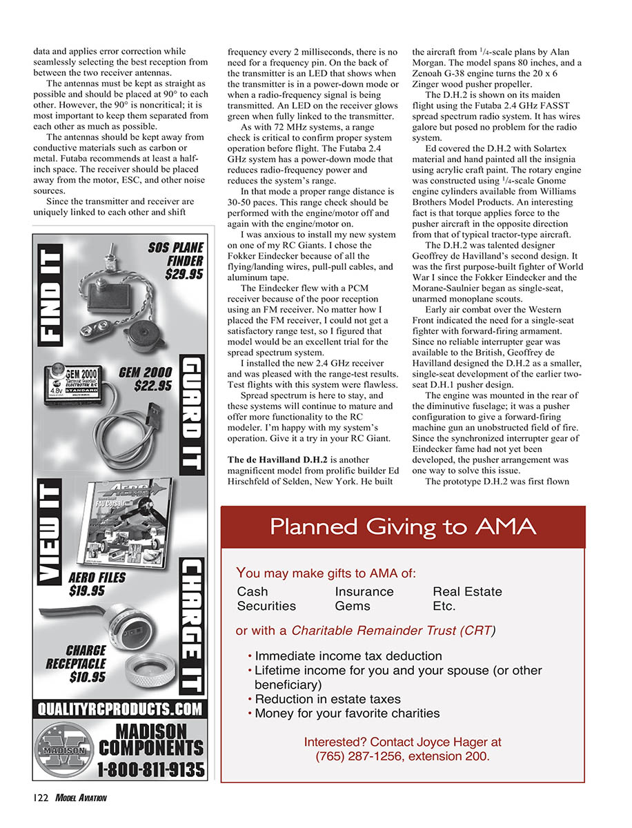
The de Havilland D.H.2 model The de Havilland D.H.2 is another magnificent model from prolific builder Ed Hirschfeld of Selden, New York. He built the aircraft from 1/4-scale plans by Alan Morgan. The model spans 80 inches, and a Zenoah G-38 engine turns a 20 x 6 Zinger wood pusher propeller. The D.H.2 was shown on its maiden flight using the Futaba 2.4 GHz FASST spread spectrum radio system. Despite having wires galore, the radio system had no problem.
Ed covered the D.H.2 with Solartex material and hand-painted all insignia using acrylic craft paint. The rotary engine was constructed using 1/4-scale Gnome engine cylinders available from Williams Brothers Model Products. An interesting operational note: torque applies force to a pusher aircraft in the opposite direction from that of a typical tractor-type aircraft.
Historical background
- The D.H.2 was Geoffrey de Havilland's second design and was the first purpose-built British fighter of World War I after the Fokker Eindecker and Morane-Saulnier scouts.
- Early air combat over the Western Front showed the need for a single-seat fighter with forward-firing armament. With no reliable interrupter gear available to the British, de Havilland designed the D.H.2 as a smaller, single-seat development of the earlier two-seat D.H.1 pusher design.
- The engine was mounted at the rear in a pusher configuration to give a forward-firing machine gun an unobstructed field of fire.
- The prototype D.H.2 first flew from Hendon Field in June 1915. It had good maneuverability and an excellent rate of climb.
- The aircraft was armed with a single Lewis machine gun and five drums of ammunition, which could be positioned on one of three flexible mountings in the cockpit. Pilots learned to aim the aircraft rather than the gun, so the gun was eventually fixed in a forward center mount (with an approved clip allowing it to be released if required).
- The D.H.2's top speed was roughly 93 mph. Later developments sought more power from the Gnome Monosoupape rotary engine; re-boring increased power but sometimes led to cylinders being shed in flight with fatal consequences.
- Newly built engines were installed in all D.H.2s flown to France by 24 Squadron RFC — the world's first fighter squadron — in late 1915. Although the type was unpopular because of limited speed and range and a tendency to spin, the D.H.2 helped end the "Fokker Scourge." Airco built roughly 400 D.H.2s.
The Spad Build Continues:
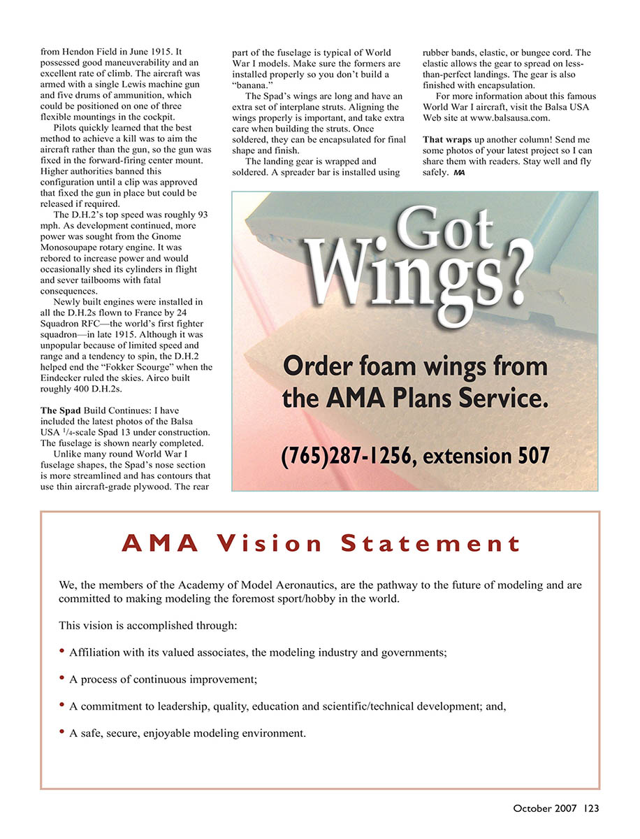
I have included the latest photos of the Balsa USA 1/4-scale Spad 13 under construction. The fuselage is nearly completed.
Notes and tips for the Spad build:
- Unlike many round World War I fuselage shapes, the Spad's nose section is more streamlined and uses thin aircraft-grade plywood for contours.
- Ensure formers are installed properly so you don't build a "banana" (warped fuselage).
- The Spad's wings are long and have an extra set of interplane struts. Align the wings properly and take extra care when building the struts.
- Once struts are soldered, they can be encapsulated for final shape and finish.
- The landing gear is wrapped and soldered. A spreader bar is installed using rubber bands, elastic, or bungee cord; the elastic allows the gear to spread on less-than-perfect landings. The gear is also finished with encapsulation.
For more information about the Spad and other World War I aircraft kits, visit the Balsa USA website at www.balsausa.com.
That wraps up another column! Send me photos of your latest project so I can share them with readers. Stay well and fly safely. MA
Transcribed from original scans by AI. Minor OCR errors may remain.

