
RADIO CONTROL: GIANTS
John A. de Vries
4610 Moffat Lane, Colorado Springs, CO 80915
It's here — a beautiful bit of British ironmongery (aluminum-mongery?). The RCV 120 engine arrived in its specially fitted foam carton, wrapped in clear plastic. RCV stands for Rotating Cylinder Valve, and is the name of the company that manufactures the engine.
RCV 120 — First impressions
Photos and drawings do not fully prepare you for the real item. The glow plug is on the bottom front of the engine, and the instructions strongly advise against trying to start the engine at the propeller. The plug is so near the propeller driver that flipping a glow plug connector off would almost certainly slap it into the prop.
Strangely for an essentially European engine, the recommended fuel should contain 5–10% nitro; most European fuels omit nitro.
The eight-page instruction manual is complete and specific about how the engine is to be run. One of the first instructions notes that a remote glow plug connection is necessary. The manual also touts the behind-the-propeller starting procedure, which leads you to design Giant Scale cowls with a circular hole in the top so the starter can poke in a couple of inches in front of the engine mount.
Installation and mounting notes
There is some concern about the 2:1 gearing of the engine. The manual instructs that the RCV be firmly mounted to the firewall without the common anti-vibration Lord/rubber mounting devices. It even recommends bolting the model's wing to the fuselage when starting; the vibrations are transmitted throughout the model and are absorbed by the attached wing. If wings are affixed with rubber bands, they will probably flap while the engine is running — so the instructions recommend that wings be bolted in place.
Because the engine is geared, props should be pitched higher than usual for a 120. The recommended break-in propeller is an 18 x 12, and a 20 x 10 is suggested as a flight propeller.
Engine configuration
The engine can be assembled to position the exhaust or carburetor to fit your installation. Although the manual cautions against disassembly, it provides step-by-step procedures for doing so. The engine is slim enough that repositioning should rarely be necessary. As provided, the exhaust and muffler are located beneath the engine, and the carburetor is mounted on top. The carburetor resembles a Perry and is set up similarly.
Because I'm writing this in mid-January, it will be a while before I can give the RCV an outdoor run-in (which includes about an hour and a half of bench running in five-minute bursts). I suspect the engine will have to be bolted to something solid; it looks to be a strong runner. I do have a run-in propeller, and it's quite a club for a four-stroke 120.
Battery-checking method from Bob Pinkus
A while back I strongly recommended that flight and transmitter batteries be checked frequently for bad cells. My advice prompted Bob Pinkus, an engineer/administrator at Wright Field, Dayton, Ohio, to suggest a better way to check RC (radio control) batteries under load than with a simple digital voltmeter. Bob flies his models from the historic Ohio airfield and checks his batteries before every flight — he has even found a dead cell after the first flight of the day.
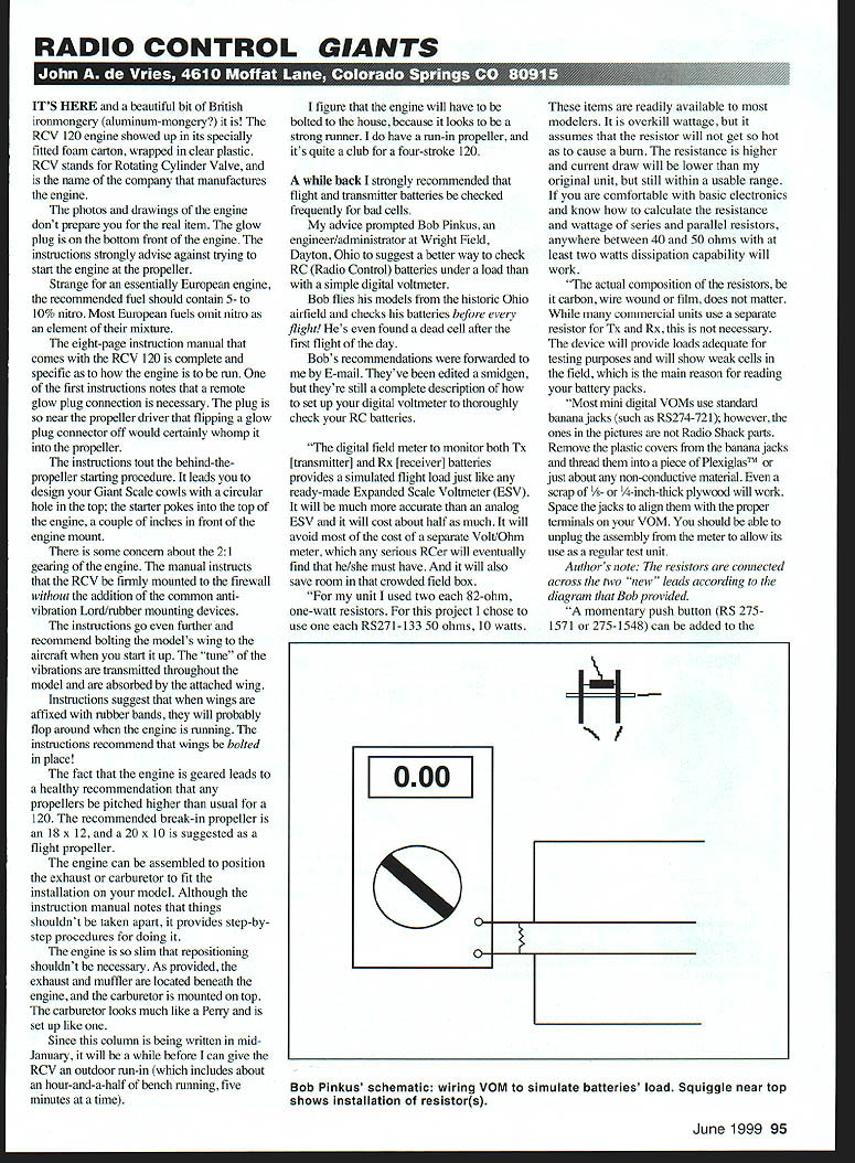
Bob's recommendations (edited slightly) describe how to set up a digital voltmeter to thoroughly check your RC batteries with a simulated flight load. The unit will be more accurate than an analog Expanded Scale Voltmeter (ESV) and will cost about half as much. It avoids most of the cost of a separate Volt/Ohm meter and saves room in a crowded field box.
Components Bob used and recommends:
- Resistors:
- Two 82-ohm, 1-watt resistors (original approach).
- Or one RS-271-133, 50-ohm, 10-watt resistor (readily available; overkill wattage is safer).
- General guidance: anywhere between 40 and 50 ohms with at least 2 watts dissipation capability will work if you are comfortable with basic electronics and calculating series/parallel resistance and wattage.
- The resistor type (carbon, wire-wound, or film) does not matter for this purpose.
- Meter connections:
- Most mini digital VOMs use standard banana jacks (such as RS-274-721). Remove the plastic covers from the banana jacks and thread them into a piece of Plexiglas or other non-conductive material (a scrap of 1/8-inch plywood will work).
- Space the jacks to align with the terminals on your meter. You should be able to unplug the assembly from the meter to allow normal use of the meter as a test unit.
- Optional switches/buttons:
- A momentary push button (RS 275-1571 or RS 275-1548) can be added to allow an instant "on" and avoid constantly toggling the meter on and off.
- If you use the push button, add an on/off slide switch (RS 275-406) in parallel so the meter can be used normally without holding the button down.
Bob's wiring puts the resistors across the two "new" leads according to the diagram he provided. He mounted the push button on the back of his meter due to space constraints; the spring in the push button was strong enough to hold the meter off until pressed. If you are not comfortable with that arrangement, do not use it — modern meters draw so little current you can just leave them on while in the field.
Practical cutoffs and display notes:
- Ni-Cd cells are generally considered dead at 1.1 volts per cell. Therefore standard cutoff voltages are:
- Transmitter (Tx): 8.8 V
- Receiver (Rx): 4.4 V
- Bob adds a 20% safety margin and stops at:
- Tx: 10.56 V
- Rx: 5.28 V
- Everybody has their own preferred cutoffs; the point is that this setup lets you read batteries under load and heed the readings.
- LCD displays do not like extreme heat or cold: they can go solid black in direct sunlight or freeze up in the cold. Keep the meter out of direct sun and other heat sources. In hot weather Bob has needed to cool the display with a rag and ice water to restore the numbers; in cold weather he has warmed it with breath and rubbing.
Final note from Bob: this circuit is intentionally simple. Simulated loads are a matter of personal preference; the variety of receivers and servos, flight conditions, and airplane build quality make it impossible to define a single true simulated load. The unit has shown a dead cell that actually developed in a two-year-old pack between flights — something a plain meter might not have detected.
Sincere thanks to Bob for providing a practical method to check R/C batteries under a simulated field load.
I had intended to continue my "war stories" describing how the airplanes I've flown actually behaved, but space constraints have delayed them until next month. See you in the July issue.
Transcribed from original scans by AI. Minor OCR errors may remain.

