
Radio Control: Helicopters
Dave Chesney
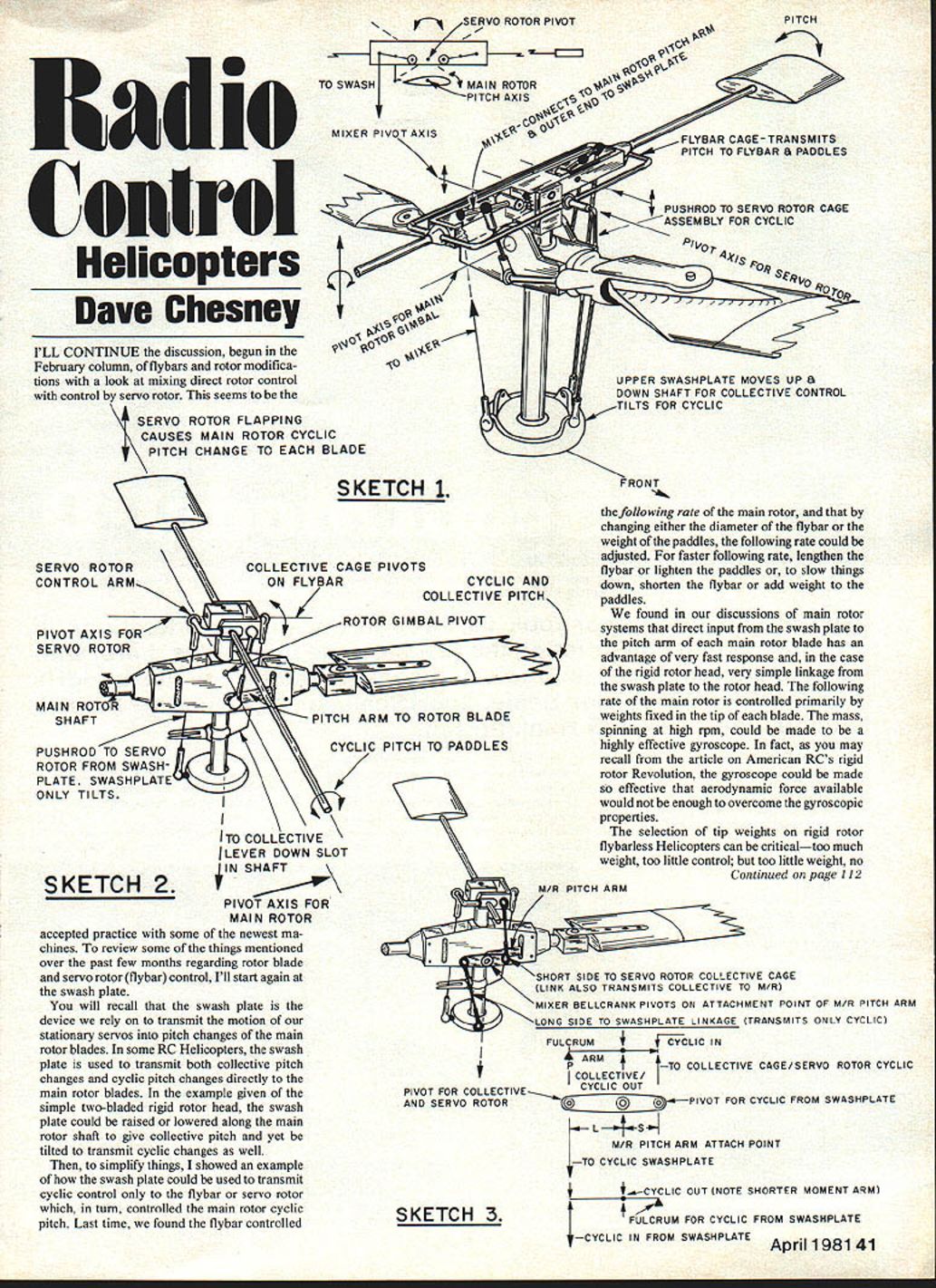
I'll continue the discussion, begun in the February column, of flybars and rotor modifications with a look at mixing direct rotor control with control by servo rotor (flybar). This seems to be the accepted practice with some of the newest machines.
Sketch 1
To review some of the things mentioned over the past few months regarding rotor blade and servo rotor (flybar) control, I'll start again at the swash plate.
You will recall that the swash plate is the device we rely on to transmit the motion of our stationary servos into pitch changes of the main rotor blades. In some RC helicopters, the swash plate is used to transmit both collective pitch changes and cyclic pitch changes directly to the main rotor blades. In the example given of the simple two-bladed rigid rotor head, the swash plate could be raised or lowered along the main rotor shaft to give collective pitch and yet be tilted to transmit cyclic changes as well.
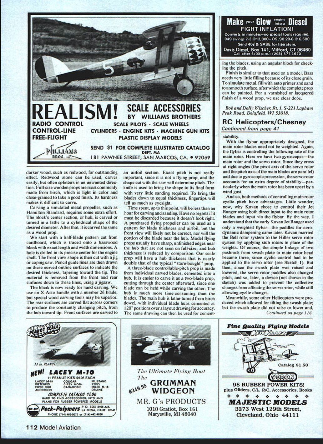
Sketch 2
To simplify things, I showed an example of how the swash plate could be used to transmit cyclic control only to the flybar or servo rotor which, in turn, controlled the main rotor cyclic pitch. Last time, we found the flybar controlled the following rate of the main rotor, and that by changing either the diameter of the flybar or the weight of the paddles, the following rate could be adjusted. For faster following rate:
- lengthen the flybar, or
- lighten the paddles.
To slow things down:
- shorten the flybar, or
- add weight to the paddles.
We found in our discussions of main rotor systems that direct input from the swash plate to the pitch arm of each main rotor blade has an advantage of very fast response and, in the case of the rigid rotor head, very simple linkage from the swash plate to the rotor head. The following rate of the main rotor is controlled primarily by weights fixed in the tip of each blade. The mass, spinning at high rpm, could be made to be a highly effective gyroscope. In fact, as you may recall from the article on American RC's rigid rotor Revolution, the gyroscope could be made so effective that aerodynamic force available would not be enough to overcome the gyroscopic properties.
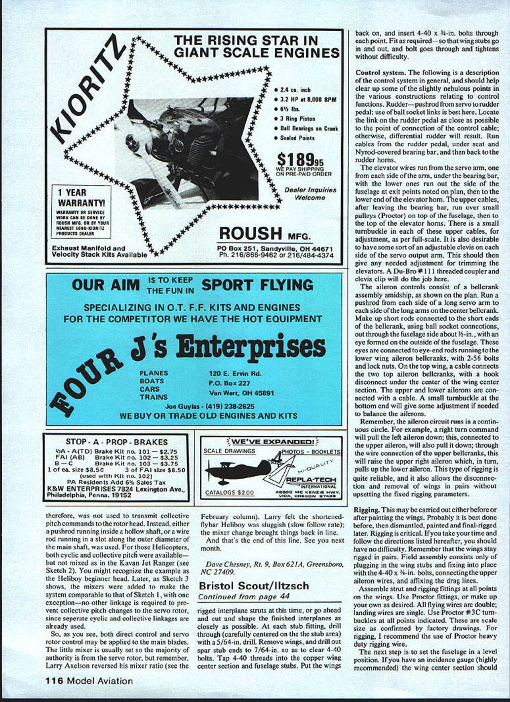
Sketch 3
The selection of tip weights on rigid-rotor, flybarless helicopters can be critical—too much weight, too little control; too little weight, no stability.
With the flybar appropriately designed, the main rotor blades need not be weighted. Again, the flybar is controlling the following rate of the main rotor. Here we have two gyroscopes—the main rotor and the servo rotor. Since they cross at right angles (the pivot axis of the servo rotor and the pitch axis of the main blades are parallel) and due to gyroscopic precession, the servo rotor accounts for an extra degree of stability—particularly when the main rotor has been upset by a wind gust.
And so, both methods of controlling main rotor cyclic pitch have advantages. Little wonder, now, why Kavan chose to control their Jet Ranger using both direct input to the main rotor blades and input via the flybar. By the way, I understand that the early Kavan Jet Ranger used only a weighted flybar—the paddles for aerodynamic damping came later. Kavan married the Bell rotor system to the Hiller servo rotor system by applying stub rotors in place of the weights. Of course, the simple linkage of two pushrods from swash plate to main rotor head became three, since cyclic control had to be applied to the servo rotor (see Sketch 1). But then, since the swash plate was raised and lowered, the servo rotor paddles also changed pitch, and so, later, a device (not shown in the sketch) was added to prevent the collective changes from affecting the servo rotor, while still allowing cyclic changes.
Meanwhile, some other helicopters were produced which allowed for tilting the swash plate; but the swash plate did not raise or lower and therefore was not used to transmit collective pitch commands to the rotor head. Instead, either a pushrod running inside a hollow shaft, or a wire rod running in a slot along the outer diameter of the main shaft, was used. For those helicopters, both cyclic and collective pitch were available—but not mixed as in the Kavan Jet Ranger (see Sketch 2). You might recognize the example as the Heliboy beginner head. Later, as Sketch 3 shows, mixers were added to make the system comparable to that of Sketch 1, with one exception—no other linkage is required to prevent collective pitch changes to the servo rotor, since separate cyclic and collective linkages are already used.
So, as you see, both direct control and servo rotor control may be applied to the main blades. The little mixer is usually set so the majority of authority is from the servo rotor, but remember, Larry Axelson reversed his mixer ratio (see the February column). Larry felt the shortened-flybar Heliboy was sluggish (slow follow rate); the mixer change brought things back in line.
And that's the end of this line. See you next month.
Dave Chesney Rt. 9, Box 6214, Greensboro, NC 27409.
Transcribed from original scans by AI. Minor OCR errors may remain.

