
Radio Control Jets
Jim Hiller [[email protected]]
Turbine feeding should consist of fuel only—no FOD!
I'm going to address turbine reliability and a common mistake I have seen: FOD (foreign object damage) to your engine. The big stuff is easy; if a bolt gets into the compressor, you will immediately see the damage. It's the smaller stuff you don't see that can do serious damage.
Grass, dirt, and sand are some of your turbine's worst enemies. Why? Because of what they can do to the bearings.
Failure of a turbine bearing is among the most serious and expensive problems that can occur. The rotating assembly consists of expensive parts in a turbine: the compressor wheel, turbine wheel, and shaft. When a bearing fails, this rotating assembly grinds to a halt, usually rubbing the turbine wheel and compressor against things they should never touch, totally destroying these expensive components.
Today's technology gives us ceramic ball bearings. These lightweight components are one of the keys to the success of bearing life and the high-RPM potential of our turbines, but they are unforgiving.
These bearings must be lubricated and kept cool. The fuel is used for lubrication, hence the need for oil mixed into it, but it's the cooling that is of interest in this conversation.
Air is bled off from behind the compressor wheel to cool the shaft bearings, entering the bearing shaft tunnel through the front bearing and exiting through the rear bearing. This technology has been developed to a highly reliable state, but it does require clean air.
The typical air that the compressor wheel sucks in is plenty clean for cooling our bearings without contaminating them under normal flying conditions. It's the air sucked in near the ground that changes all that.
A turbine is like a powerful vacuum cleaner. When the intakes are near the ground, they can suck all the dirt, sand, and grass from the ground into the compressor and through the bearings. That debris will destroy our wonderful ceramic bearings in short order—usually on the next flight when full power is needed most, costing you not only an expensive turbine repair, but possibly an airplane.
So what can you do to preserve your bearings? Don't do anything dumb!
Be conscious of the surface on which you are running up your turbine. If you fly from grass or sandy surfaces, avoid full-throttle run-ups unless they are absolutely necessary. Why make all that noise, knowingly cleaning all the garbage off the tarmac, just to hear your turbine spin up to full throttle? Save it for takeoff.
The biggest mistake I see is pilots not shutting down their turbines when they have trouble with landing gear. Many times I have seen a modeler land a jet in the grass with the landing gear up, and the crowd applauds. The pilot walks over to the model, picks it up, and then shuts down the turbine. This looks unbelievable when the model is an F-15 Eagle with the intakes resting on the ground, sucking everything it can into the turbine and those precious bearings. That modeler is shortly complaining about the poor bearing life that particular brand of turbine has and how he or she has never abused that engine.
I believe strongly in shutting down my turbine whenever I have a problem with landing gear, because it does two things. First, it allows the model to slow to a stop on landing as quickly as possible, with no residual thrust and reducing airframe damage. Second, a turbine during the cooldown process is not moving much air. Hence it does not tend to suck in all the undesirable dirt, grass, and sand that is on the ground.
I am not saying that when the nose gear fails, extend your jet's climb to 500 feet and shut down the turbine. Shut it down when you commit to land. In these situations I like to shut down the turbine just before I pull on the elevator for the final flare to land. Think about your turbine and how to avoid damaging it when you go off the runway.
ElectroDynamics EDR-106 and EDR-125
At the Toledo Show this year, I stopped by the ElectroDynamics booth to pick up a servo reverser for my T-33. Late last year I had a flap-servo failure—the reversed servo—so instead of replacing this special-order part, I purchased a servo reverser and installed two new standard units.
EDR-106 Pro Servo Reverser
ElectroDynamics makes a nice product: the EDR-106 Pro Servo Reverser. It's available as both a direct, in-line, plug-in unit or, at a slight premium, a Y-connector unit with one plug standard and one reversed. I chose the latter, which cleaned up my wiring harness in the T-33 and allowed me to set up with two fresh servos on the flaps.
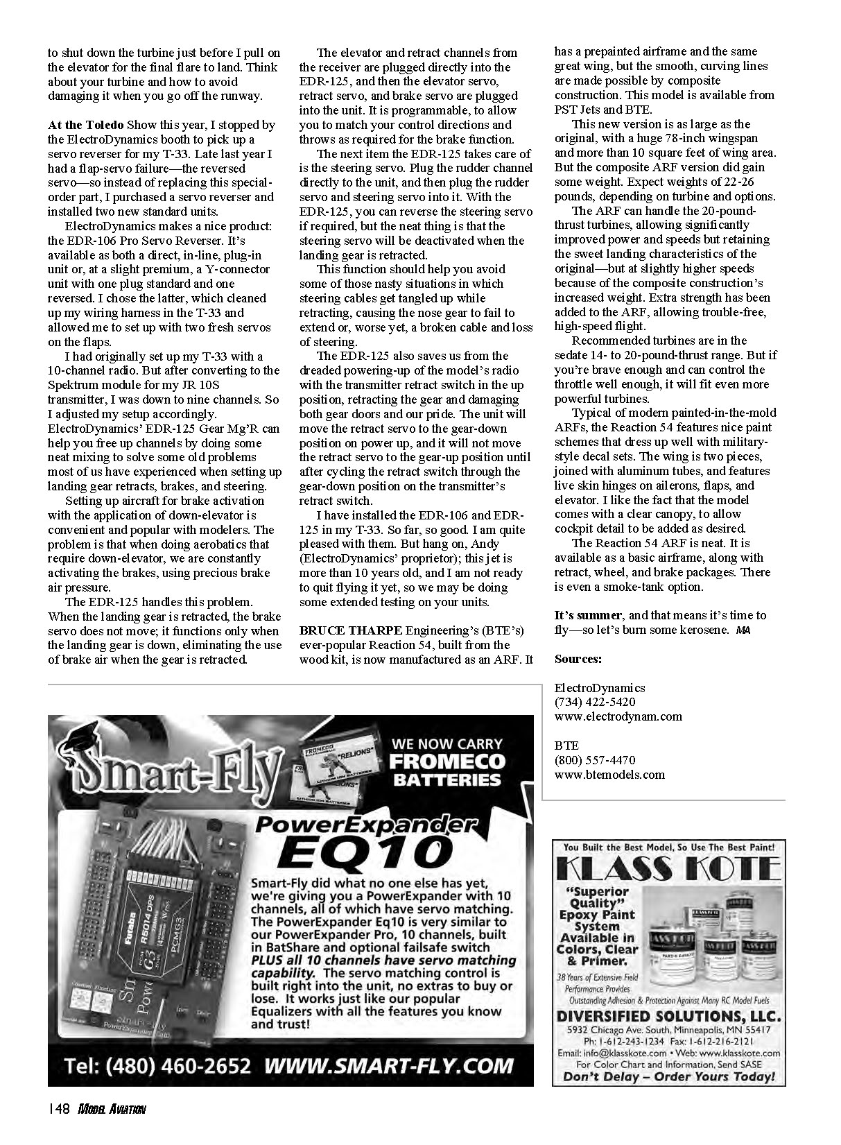
EDR-125 Gear Mg'R
I had originally set up my T-33 with a 10-channel radio. But after converting to the Spektrum module for my JR 10S transmitter, I was down to nine channels. So I adjusted my setup accordingly. ElectroDynamics' EDR-125 Gear Mg'R can help you free up channels by doing some neat mixing to solve some old problems most of us have experienced when setting up landing gear retracts, brakes, and steering.
Key functions of the EDR-125:
- Brake control tied to gear position: When the landing gear is retracted, the brake servo does not move; it functions only when the landing gear is down, eliminating the use of brake air when the gear is retracted.
- Steering deactivation: Plug the rudder channel directly to the unit, then plug the rudder servo and steering servo into it. The steering servo will be deactivated when the landing gear is retracted, helping avoid tangled steering cables during retraction.
- Power-up safety: The unit moves the retract servo to the gear-down position on power-up and will not move the retract servo to gear-up until after cycling the retract switch through gear-down on the transmitter.
- Programmable: The unit is programmable to match control directions and throws as required for the brake function. It can also reverse the steering servo if required.
I have installed the EDR-106 and EDR-125 in my T-33. So far, so good. I am quite pleased with them.
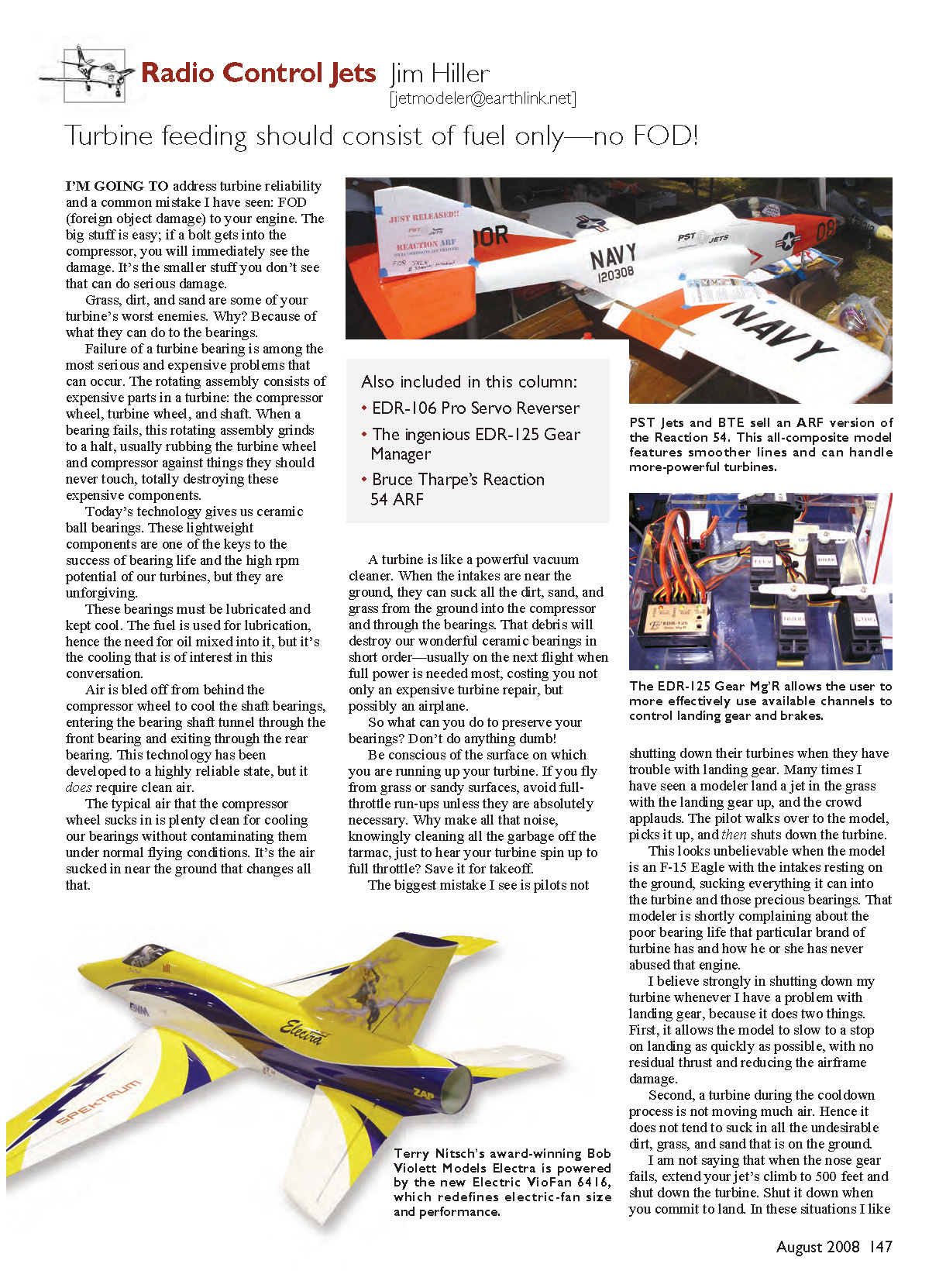
BTE Reaction 54 ARF
BRUCE THARPE Engineering's (BTE's) ever-popular Reaction 54, built from the wood kit, is now manufactured as an ARF. It has a prepainted airframe and the same great wing, but the smooth, curving lines are made possible by composite construction. This model is available from PST Jets and BTE.
Highlights and specifications:
- Size: 78-inch wingspan and more than 10 square feet of wing area.
- Weight: Expect 22–26 pounds, depending on turbine and options (composite ARF gained some weight versus the wood kit).
- Power: The ARF can handle 20-pound-thrust turbines, allowing significantly improved power and speeds while retaining the sweet landing characteristics of the original. Recommended turbines are in the 14- to 20-pound-thrust range. It will accept more powerful turbines if you can control the throttle.
- Construction and features:
- Composite construction with extra strength for high-speed flight.
- Painted-in-the-mold schemes that dress up well with military-style decal sets.
- Two-piece wing joined with aluminum tubes.
- Live-skin hinges on ailerons, flaps, and elevator.
- Clear canopy included to allow cockpit detail to be added as desired.
- Options: Available as a basic airframe, with retract, wheel, and brake packages. A smoke-tank option is also available.
The Reaction 54 ARF is neat and ready for summer flying—so let's burn some kerosene.
Sources
- ElectroDynamics
(734) 422-5420 www.electrodynam.com
- BTE
(800) 557-4470 www.btemodels.com
Transcribed from original scans by AI. Minor OCR errors may remain.

