

An oldie gets the total turbine workup
Jim Hiller ([email protected])
In the previous column (April issue) I mentioned my latest project: converting a BVM Jets Maverick to turbine power. I have been pushing that a little, but I can’t resist the urge to change things.
This Maverick was changed to turbine power in the simplest way: a tailpipe was added, a turbine was installed in front of the tailpipe, and a 50-ounce fuel tank was placed in front of the turbine. The original inlets had approximately 2 inches removed, which made them basically nonexistent.
This setup worked because the jet did fly, but man was it slow — it flew maybe 130–140 mph, not up to jet standards. That was the state of the Maverick when I got it. Now it’s time for some fun.
The first thing I did was remove the 50-ounce fuel tank and make two fiberglass saddle tanks to accommodate 32 ounces each, freeing space for proper inlets. Then I fabricated new inlets from fiberglass, in a typical "Y" setup, running back to the turbine.
With that work done, I took the model out to the field for a few flights. Oh yeah! What a performance difference it makes to manage the air coming through the airframe back to the turbine. The Maverick obtained speed and much better vertical performance.
But alas, all was not well. The saddle tanks feeding directly into a 2-ounce header tank left me with big air-bubble issues. That little header tank wasn’t up to the task.
Now the Maverick is in the shop for Round Two: to make room for a bigger header tank, new wings, and a complete repaint.
New wings? Why not? I like them. The stock straight wings on a Maverick never thrilled me; swept wings look fast. I’ll give you more information about the conversion as it happens.
Fiberglass molding — getting started
Molding your own fiberglass parts is not that difficult; it’s merely different from working with balsa. Go ahead and try it.
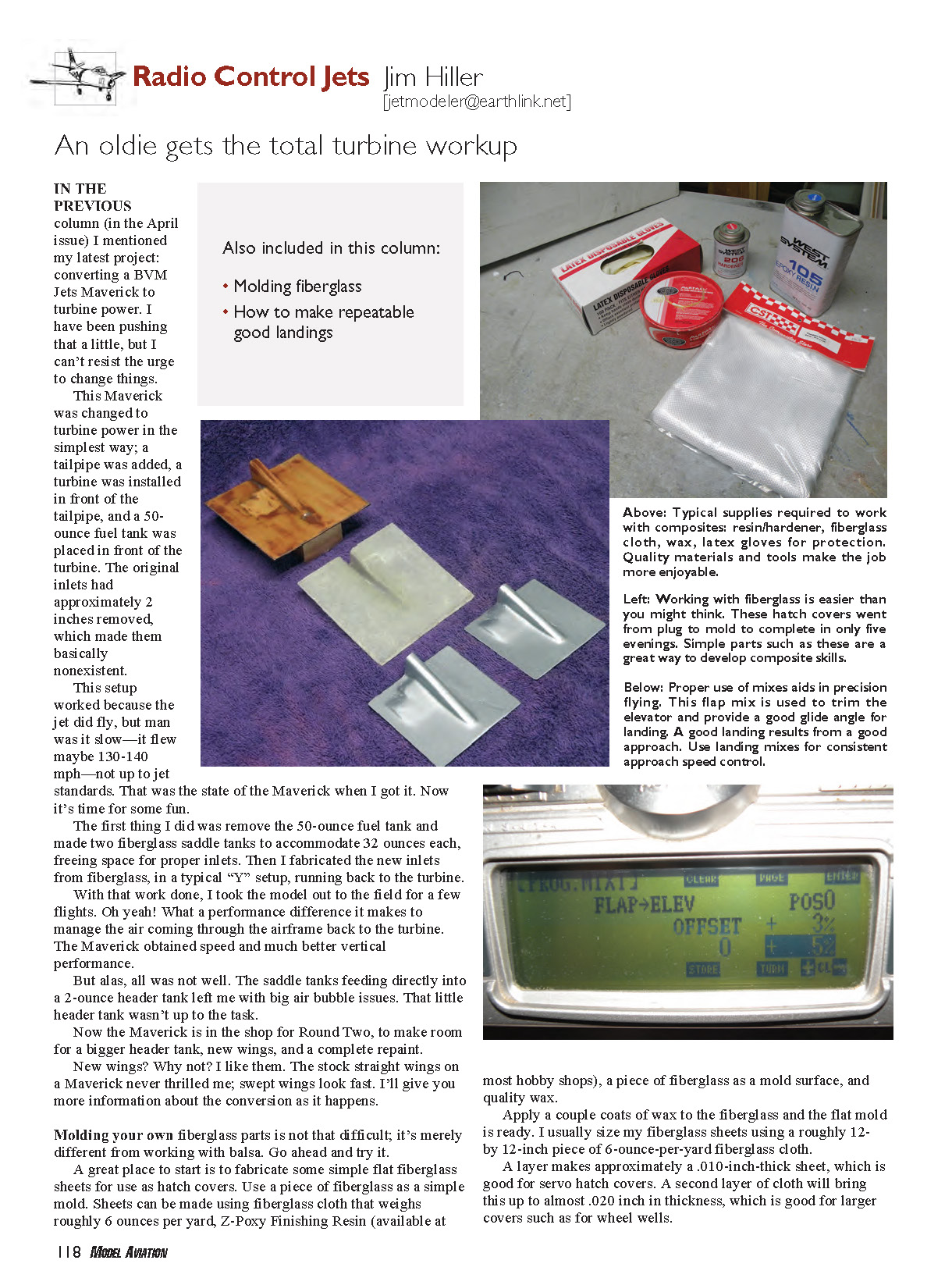
A great place to start is to fabricate some simple flat fiberglass sheets for use as hatch covers. Use a piece of fiberglass as a simple mold. Sheets can be made using fiberglass cloth that weighs roughly 6 ounces per yard, Z-Poxy Finishing Resin (available at most hobby shops), a piece of fiberglass as a mold surface, and quality wax.
Apply a couple coats of wax to the fiberglass; the flat mold is then ready. I usually size my fiberglass sheets using a roughly 12-by-12-inch piece of 6-ounce-per-yard fiberglass cloth. A single layer makes approximately a .010-inch-thick sheet, which is good for servo hatch covers. A second layer of cloth will bring this up to almost .020 inch in thickness, which is good for larger covers such as wheel wells.
Put on a pair of latex disposable gloves before you mix the finishing resin. That will keep your hands clean, which is a must if working with fiberglass and resin is to be enjoyable. Position the first layer of fiberglass cloth in place on the fiberglass mold area, then pour mixed finishing resin onto the cloth. Spread the resin with something similar to an old credit card. I use hard 1/8-inch balsa cut to 3-inch lengths, but almost anything will do. Work the resin through the cloth. Work the excess off the edges or soak up extra resin with paper to minimize resin content and keep the weight of the finished panel to a minimum.
Add the second layer of cloth if a thicker piece is required. Use the same technique as before, but add the second layer when the first just gets tacky; the second layer will bond better.
Let the whole thing cure for 24 hours and then remove it from the mold. Now you have some nice fiberglass material for hatch covers.
Shaped hatch covers and hiding control linkage
That worked well. How about getting more complicated and molding shaped hatch covers that also hide the control linkage? That's what I did last winter on my old BVM BobCat; I fabricated new elevator hatch covers to hide the oversize JR8411 servos I had installed.
With this level of work, I suggest ordering supplies from a composite supplier to get more specialized materials. I chose West System Epoxy 105 Resin with the slow 205 Hardener, for maximum working time. Those products are available from The Composites Store.
For a wax release agent, I’ve been using Rexco Partall mold release wax. One container will last decades, given the few composite parts I make.
A selection of 2-, 4-, and 6-ounce fiberglass cloth will go a long way toward providing options as you tackle different projects, along with CAB-O-SIL that is used as a filler.
To start this shaped-hatch project, I measured the shape required to clear the servo and linkage and used that information to make the plug. Do not overcomplicate the materials required to make the mold; use whatever is easiest to shape.
The base of my plug is a piece of 1/8-inch plywood, to which I added balsa to provide servo-clearance humps and a 5/16-inch triangle balsa piece to clear the elevator linkage that extends all the way back to the control horn.
My plug is finished with three coats of the finishing resin. I didn't even bother to paint it; I did a final sanding with 600- and 1,500-grit sandpaper to knock off some dirt, and applied six coats of wax. Then it was time to make the mold.
I fabricated the mold by putting pieces of 2-ounce cloth over the plug: one piece for the linkage triangle and one piece with a clearance slot for the flat hatch cover. I used two pieces of cloth so I would not have to force a single piece of fiberglass cloth to conform to this complicated shape.
Practice getting the cloth to lay against the plug before mixing resin and applying it to the material. Mix the resin and apply the first layer. An acid brush is good for applications on small parts such as these.
Let the resin cure for roughly an hour until it gets tacky, then lay on multiple layers of cloth to make the mold rigid. Let this mold cure for approximately 24 hours before removing the mold from the plug.
The mold is complete. It's time to make parts.
Apply six to eight coats of wax. For this hatch cover, I cut two 6-ounce layers of cloth: one for the deep-draw triangle linkage cover and one for the generally flat main hatch cover, with the slot where the deep draw of the mold is. Carefully lay the fiberglass cloth in place and brush in the resin.
If things don't lay properly on the first piece and you get voids, it's no big deal; learn from this bad piece and try again. That's what makes having the mold so great. Now you can make as many identical parts as you want.
Supplies and materials (suggested)
- Fiberglass cloth: 2-, 4-, and 6-ounce varieties
- Z-Poxy Finishing Resin (or West System Epoxy 105 with 205 slow hardener)
- Wax release agent (Rexco Partall mold release wax)
- CAB-O-SIL filler
- Latex disposable gloves
- Mixing and spreading tools (old credit card, 1/8-inch balsa sticks, acid brush)
- Sandpaper: 600- and 1,500-grit
Flying Tips — setting up a jet for good, repeatable landings
How do you set up a jet to make good, repeatable landings? Nothing is worse than fighting your airplane to maintain proper airspeed, descent rate, heading, and runway alignment, all at the same time.
Varying airspeeds affect the final flare: higher speed means more float — more time and inches off the runway trying to bleed off excess airspeed; lower speed might mean not enough speed to even flare at all. Get behind the jet on approach and the landing gets ugly.
Let's work on airspeed. You don't have to fight it; set up your model correctly and let it do the work for you.
My jets are trimmed so that when I enter the traffic pattern for landing, I don't have to touch the elevator except to hold the nose up in the turns. Then when the aircraft is close to waist height, I merely pull the elevator to initiate the landing flare. That takes the inconsistency out of gliding the model in for landing by trying to hold a consistent elevator to control angle of attack all the way around the pattern. Airspeed control requires a great amount of workload in the traffic pattern; inconsistency in airspeed greatly affects the reaction of the elevator and the distance of float down the runway during the final flare.
When I was a kid, I trimmed balsa hand-launch gliders to glide after gaining altitude. I do the same for my jets, but now I can do it with transmitter mixes. I'll use my BVM Jets T-33 setup as an example of how it can be done.
I found that with flap application, the nose tended to pitch down. So let's use a mix to apply up-elevator with flap deflection.
My radio is a JR 10X, so the mix is based from a center position or approximately half flaps. This complicates things a bit but adds greater flexibility for trimming to the glide.
I start with the flaps retracted and roughly a 3% down-elevator mix. That affected my normal trim, so I had to retrim the elevator for level flight. This gave a nice, level glide, although a bit fast at half flaps. It was great for entering the traffic pattern with minimal effect to my level flight.
As the landing gear is extended, the T-33 slows. That means it's time to fully extend the flaps, and with that I have an additional 5% up-elevator mix. In this state, the T-33 will maintain level flight as it slows to a comfortable glide speed.
The jet is now gliding with no elevator input from me; I've used the mixes to trim the T-33 for a perfect glide speed for the landing approach, and my workload is reduced. I can now concentrate on aligning the model to the runway for that perfect approach to landing.
That sounds too simple, and it is. It took quite a few flights before I got the mix setup where I like it, but it is wonderful now!
One effect of this is that I know how much fuel is left when I enter the crosswind leg for landing. Most of the fuel in this model is forward of the CG, so the glide speed is an indication of how much fuel is remaining — more fuel, nose-heavy, faster glide; less fuel, more tail-heavy, slower glide. I can use this information to adjust my initiation for the final flare.
When the T-33 is gliding slower, I will have less airspeed to fiddle with during the flare. So I will initiate the elevator pull slightly lower, to allow a gentle leveling off during the flare before I run out of airspeed.
I have one more trick. When the jet is landing heavy, with more fuel onboard (typical when flying at a jet meet), my speed board function is programmed to give me another 2% up-elevator trim, so I can make a fine adjustment to the glide speed by adding the speed boards. Maybe I've been flying this T-33 for way too long; I definitely have it dialed in.
It's summer and the jets are packed, so let's get out and fly.
MA
Sources
- BVM Jets
(407) 327-6333 www.bvmjets.com
- The Composites Store
(800) 338-1278 www.cstsales.com
- Rexco
(800) 888-1060 www.rexco-usa.com
- Jet Pilots Organization
Transcribed from original scans by AI. Minor OCR errors may remain.

