
Radio Control Jets - 2012/02
By Jim Hiller ([email protected])
E-Jets International is still a fun event
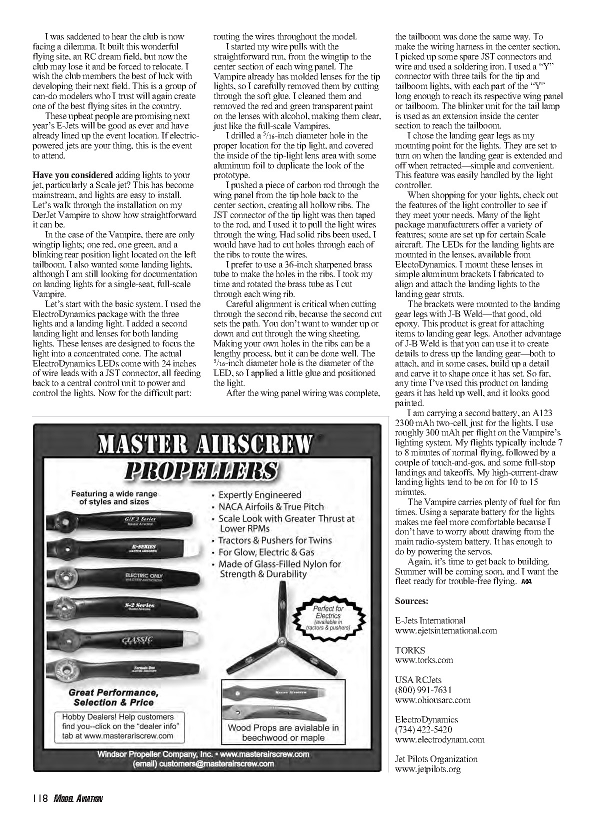
I finally did it. I attended E-Jets International—an electric-powered, ducted-fan event in Grove City, Ohio, where turbines aren't welcome—for the first time, thanks to the prodding of my friends Doug Drenth and Billy DiRenzo. They promised me access to their new Jet Teng Viper prototype, along with a Jet Teng Hawk. Both airplanes are well set up, 90mm ducted-fan models, manufactured by their company, USA RCJets.
They have been trying to convince me to become an electric-powered jet pilot for years. They are close, but I've not quite converted.
I helped both Billy and Doug get their turbine waivers last fall, following E-Jets. Congratulations!
The Hawk has a Stumax 90mm fan and motor with a Castle Creations speed controller, and is powered by an XPS 10-cell, 4,000 mAh setup—great for a comfortable six minutes of flying. We flew this model in the speed runs; it ran well at roughly 150 mph straight and level with this setup. It's an impressive flying machine that not only looks good, but hauls well.
The Viper jet had the 90mm HET fan setup, again with an XPS 10-cell, 4,000 mAh battery. It had similar performance, but in an aerobatic airframe. Both aircraft weigh approximately 10.5 pounds with batteries and have better than a 1:1 power-to-weight ratio. It's fun to embrace the power on these models, because they carry speed well and full power is only required on the verticals.
Back to the E-Jets speed runs; it sure was fun to do that again. I haven't made a speed run since the old internal-combustion, ducted-fan speed days. The only thing missing was the sound of a BVM .91 unloading in the big dive, and yes, that was part of the speed runs, too.
Qualifying and all runs, from left to right, were made from an entry level of approximately 100 feet. Dropping down coming out of the turn to the pass gave a realistic measure of the level-speed potential of the pilot and aircraft. While our little Hawk whipped off 150+ mph speeds, those big Bob Violett Models Electras recorded passes in the 170-mph range. Those electric-powered ducted fans do move out! During the finals, passes from right to left had to be made from a split S to avoid flying over a nearby house; off with the gloves and let them rip. It was fun to see the Unlimited class aircraft diving out of the sky at speeds of more than 220 mph. It was just as much fun as the old days, and great to see the speed runs alive and well.
E-Jets is a fun, well-organized event hosted by The Ohio Radio Kontrol Society (TORKS) club. It was good to see many of the club members. It has been quite a few years since I last attended one of the club's events.
I was saddened to hear the club is now facing a dilemma. It built this wonderful flying site—an RC dream field—but now the club may lose it and be forced to relocate. I wish the club members the best of luck with developing their next field. This is a group of can-do modelers who I trust will again create one of the club's dream fields. These upbeat people are promising next year's E-Jets will be as good as ever and have already lined up the event location. If electric-powered jets are your thing, this is the event to attend.
Have you considered adding lights to your jet, particularly a Scale jet?
This has become mainstream, and lights are easy to install. Let's walk through the installation on my DerJet Vampire to show how straightforward it can be.
In the case of the Vampire, there are only wingtip lights—one red, one green—and a blinking rear position light located on the left tailboom. I also wanted some landing lights, although I am still looking for documentation on landing lights for a single-seat, full-scale Vampire.
Basic system I used the ElectroDynamics package with the three position lights and a landing light. I added a second landing light and lenses for both landing lights. These lenses are designed to focus the light into a concentrated cone. The ElectroDynamics LEDs come with 24 inches of wire leads and a JST connector, all feeding back to a central control unit to power and control the lights. Now for the difficult part: routing the wires throughout the model.
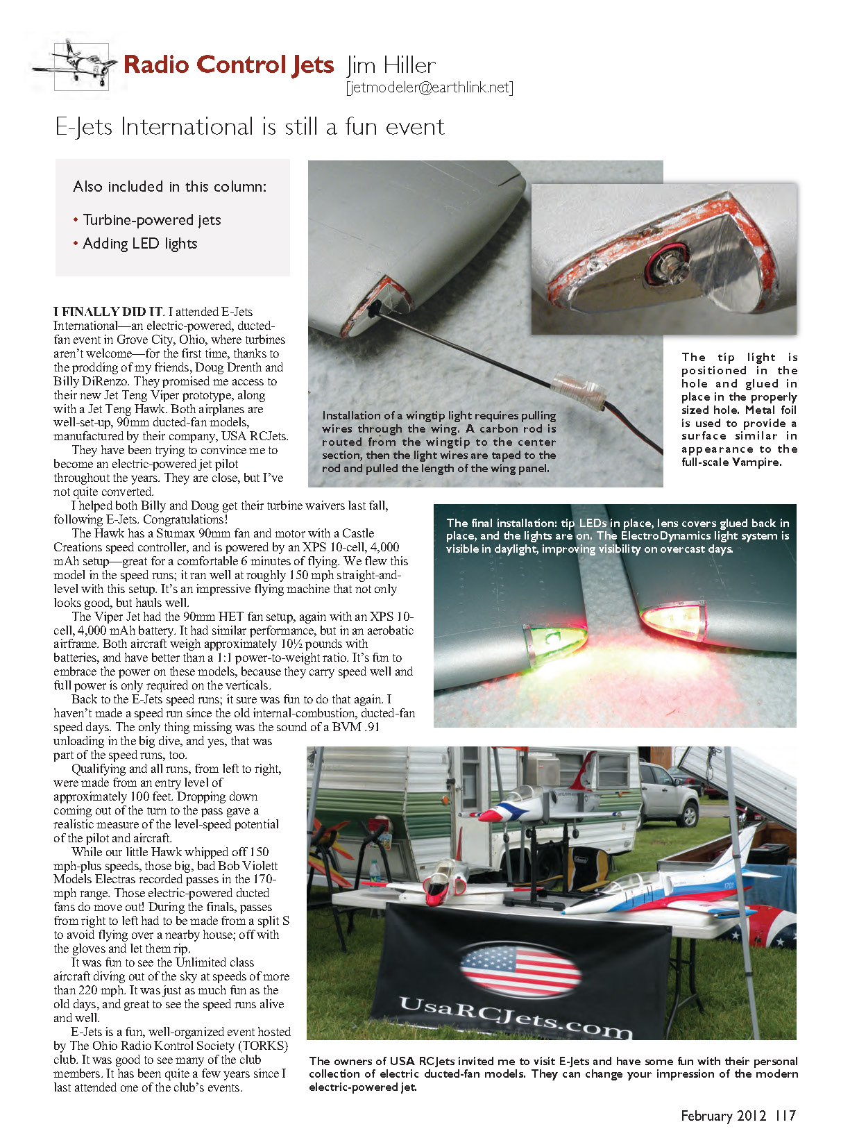
Wiring the wingtips I started my wire pulls with the straightforward run from the wingtip to the center section of each wing panel. The Vampire already has molded lenses for the tip lights, so I carefully removed them by cutting through the soft glue. I cleaned them and removed the red and green transparent paint on the lenses with alcohol, making them clear, just like the full-scale Vampires.
I drilled a 5/16-inch diameter hole in the proper location for the tip light, and covered the inside of the tip-light lens area with some aluminum foil to duplicate the look of the prototype.
I pushed a piece of carbon rod through the wing panel from the tip hole back to the center section, creating a path through hollow ribs. The JST connector of the tip light was then taped to the rod, and I used it to pull the light wires through the wing. Had solid ribs been used, I would have had to cut holes through each of the ribs to route the wires.
I prefer to use a 3/16-inch sharpened brass tube to make the holes in the ribs. I took my time and rotated the brass tube as I cut through each wing rib. Careful alignment is critical when cutting through the second rib, because the second cut sets the path. You don't want to wander up or down and cut through the wing sheeting. Making your own holes in the ribs can be a lengthy process, but it can be done well. The 5/16-inch diameter hole is the diameter of the LED, so I applied a little glue and positioned the light.
Tailboom and center harness After the wing panel wiring was complete, the tailboom was done the same way. To make the wiring harness in the center section, I picked up some spare JST connectors and wire and used a soldering iron. I used a "Y" connector with three tails for the tip and tailboom lights, with each part of the "Y" long enough to reach its respective wing panel or tailboom. The blinker unit for the tail lamp is used as an extension inside the center section to reach the tailboom.
Landing lights and switching I chose the landing gear legs as my mounting point for the landing lights. They are set to turn on when the landing gear is extended and off when retracted—simple and convenient. This feature was easily handled by the light controller.
When shopping for your lights, check the features of the light controller to see if they meet your needs. Many light package manufacturers offer a variety of features; some are set up for certain scale aircraft. The LEDs for the landing lights are mounted in the lenses, available from ElectroDynamics. I mount these lenses in simple aluminum brackets I fabricated to align and attach the landing lights to the landing gear struts.
The brackets were mounted to the landing gear legs with J-B Weld, that good old epoxy. This product is great for attaching items to landing gear legs. Another advantage of J-B Weld is that you can use it to create details to dress up the landing gear—both to attach and, in some cases, to build up a detail and carve it to shape once it has set. So far, any time I've used this product on landing gear it has held up well, and it looks good painted.
Power for the lights I carry a second battery, an A123 2300 mAh two-cell, just for the lights. I use roughly 300 mAh per flight on the Vampire's lighting system. My flights typically include seven to eight minutes of normal flying, followed by a couple of touch-and-gos, and some full-stop landings and takeoffs. My high-current-draw landing lights tend to be on for 10 to 15 minutes.
The Vampire carries plenty of fuel for fun times. Using a separate battery for the lights makes me feel more comfortable because I don't have to worry about drawing from the main radio-system battery. It has enough to do by powering the servos.
Again, it's time to get back to building. Summer will be coming soon, and I want the fleet ready for trouble-free flying.
Sources
- E-Jets International — www.ejetsinternational.com
- TORKS — www.torks.com
- USA RCJets — (800) 991-7631 — www.usarcjets.com
- ElectroDynamics — (734) 422-5420 — www.electrodynamics.com
- Jet Pilots Organization — www.jetpilots.org
Transcribed from original scans by AI. Minor OCR errors may remain.

