
Radio Control Pylon Racing - 2010/10
Aaron "AJ" Seaholm [[email protected]]
Also included in this column:
- Judgeman system
- Old Julian Airport races
Great Planes Viper 500: ARF vs. RTC
Background
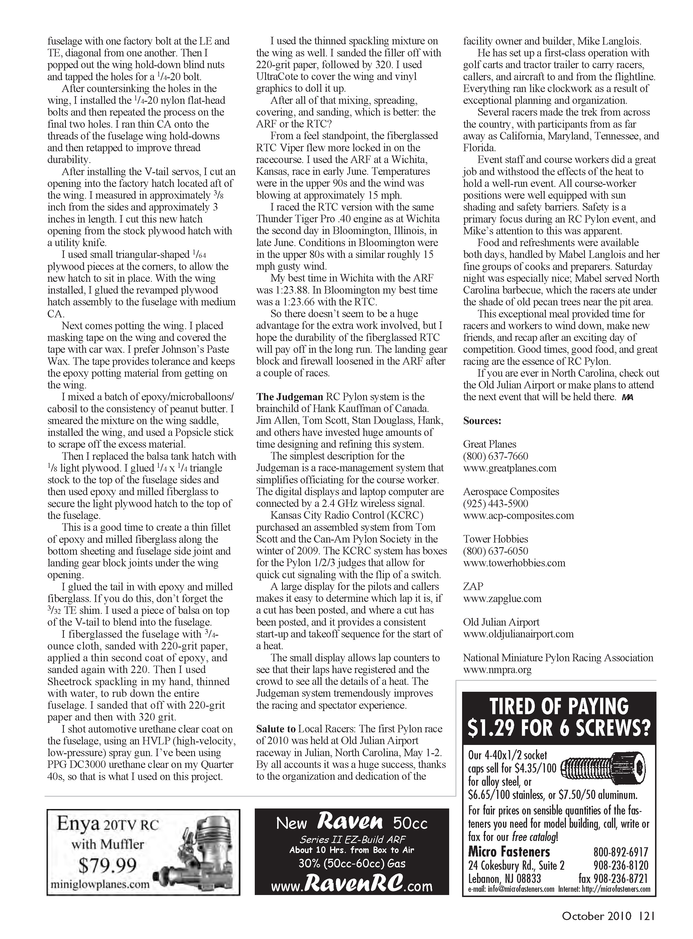
I have raced the Great Planes Viper 500 ARF in local Sport Quickie (AMA event 424) contests for approximately three seasons. I recently purchased a Viper 500 Ready-to-Cover (RTC) version for a Sport Quickie backup and eventual use in the evolving Sport Jet Quickie 500 class.
I was impressed with the Viper RTC package and construction. It comes ready for strengthening, meaning there is no reinforcing fiberglass as on the ARF version.
To describe the materials used for reinforcement, I will start at the nose of the model and work my way back. The epoxy strengtheners and fillers I describe were bought from Aerospace Composites and Tower Hobbies. I used Zap Z-Poxy Finishing Resin in all of the epoxy mixtures described below.
Nose reinforcement
In the nose, before installing the top hatch, I used epoxy and chopped carbon fiber. The goal is to wet the chopped carbon enough to securely bond it to the firewall and fuselage sides.
This mixture can be challenging to position. The best method is to wet your fingertip with isopropyl alcohol and move the material to form the fillets.
Wing and aileron torque rods
The aileron torque rods installed in the wing were not tight. I used an X-Acto knife to remove 1/8 x 3/8-inch pieces of balsa to expose the torque rod near the center section and the aileron intersection.
I used a small brush to apply car wax to the torque rod (Vaseline also works well), then filled the opening down to the torque rod with an epoxy/microballoons/cabosil mixture. This creates bushings at both ends of the tube and minimizes slop.
Note: cabosil (sometimes called aerosil) is a thickening additive that helps keep the epoxy from flowing. The microballoon mixture works well where strength is noncritical and sanding might be required.
I fiberglassed the wing with 3/4-ounce cloth, top and bottom. The top cloth pattern was approximately 12 inches wide at the leading edge (LE), tapering back to 6 inches at the trailing edge (TE). The bottom piece was a constant 8 inches in width.
Spread the finishing resin with an old credit card or hotel-room key and try to pull off as much resin as possible. The strength is in the fiberglass, but you need enough resin to turn the fiberglass from cloth into a stiff composite.
V-tail work
I glued the V-tail into the fuselage to help strengthen this known weak area. I removed the plywood cap from the center section of the V-tail with a 3/8-inch-wide wood chisel to allow for the standard 3/32-inch shim required under the TE to get the V-tail incidence correct.
If you don't shim the TE, the Viper will carry a substantial amount of up-elevator trim during flight. I also trimmed approximately 1 inch off the V-tail tips and rounded them to match the shape of the wingtips.
I fiberglassed the V-tail with 3/4-ounce cloth top and bottom. Before that, I tack-glued the elevators to the V-tail assembly with thin CA and sanded down the LE and TE ridges. The bevel in the factory elevators fills with resin during the fiberglass process and can be challenging to cut off.
Wing bolts and hold-downs
The factory aluminum wing bolts have a tendency to back out during flight. I bolted the wing to the fuselage with one factory bolt at the LE and one at the TE diagonally opposite each other. Then I popped out the wing hold-down blind nuts and tapped the holes for 1/4-20 bolts.
After countersinking the holes in the wing, I installed 1/4-20 nylon flat-head bolts and repeated the process on the remaining two holes. I ran thin CA onto the threads of the fuselage wing hold-downs and then retapped to improve thread durability.
Hatch and servo access
After installing the V-tail servos, I cut an opening into the factory plywood hatch located aft of the wing. I measured in approximately 3/8 inch from the sides and about 3 inches in length, and cut the new hatch opening from the stock plywood hatch with a utility knife.
I used small triangular 1/64-inch plywood pieces at the corners so the new hatch would sit in place. With the wing installed, I glued the revamped plywood hatch assembly to the fuselage with medium CA.
Potting the wing and tank hatch
Next comes potting the wing. I placed masking tape on the wing saddle and covered the tape with car wax (I prefer Johnson’s Paste Wax). The tape provides tolerance and keeps the epoxy potting material from getting on the wing.
I mixed epoxy/microballoons/cabosil to the consistency of peanut butter, smeared the mixture on the wing saddle, installed the wing, and used a Popsicle stick to scrape off excess material.
Then I replaced the balsa tank hatch with 1/8-inch light plywood. I glued 1/4 x 1/4 triangle stock to the top of the fuselage sides and used epoxy and milled fiberglass to secure the light plywood hatch to the top of the fuselage.
This is a good time to create a thin fillet of epoxy and milled fiberglass along the bottom sheeting/fuselage side joint and landing gear block joints under the wing opening.
I glued the tail in with epoxy and milled fiberglass. If you do this, don’t forget the 3/32-inch TE shim. I used a piece of balsa on top of the V-tail to blend into the fuselage.
Fiberglassing and finishing
I fiberglassed the fuselage with 3/4-ounce cloth, sanded with 220-grit paper, applied a thin second coat of epoxy, and sanded again with 220. Then I used Sheetrock spackling, thinned with water, to rub down the entire fuselage by hand. I sanded that off with 220-grit paper, followed by 320-grit.
I shot automotive urethane clear on the fuselage using an HVLP (high-velocity, low-pressure) spray gun. I’ve been using PPG DC3000 urethane clear on my Quarter 40s, so that is what I used on this project.
I used the thinned spackling mixture on the wing as well, sanding it off with 220-grit followed by 320. I covered the wing with UltraCote and applied vinyl graphics.
Flight impressions: ARF vs. RTC
After all that mixing, spreading, covering, and sanding, which is better: the ARF or the RTC?
From a feel standpoint, the fiberglassed RTC Viper flew more locked in on the racecourse. I used the ARF at a Wichita, Kansas, race in early June; temperatures were in the upper 90s with winds around 15 mph. I raced the RTC version with the same Thunder Tiger Pro .40 engine used at Wichita during the second day in Bloomington, Illinois, in late June. Conditions in Bloomington were in the upper 80s with similar roughly 15 mph gusty wind.
My best time in Wichita with the ARF was 1:23.88. In Bloomington my best time was 1:23.66 with the RTC.
So there doesn’t seem to be a huge advantage for the extra work involved, but I hope the durability of the fiberglassed RTC will pay off in the long run. The landing gear block and firewall loosened in the ARF after a couple of races.
The Judgeman
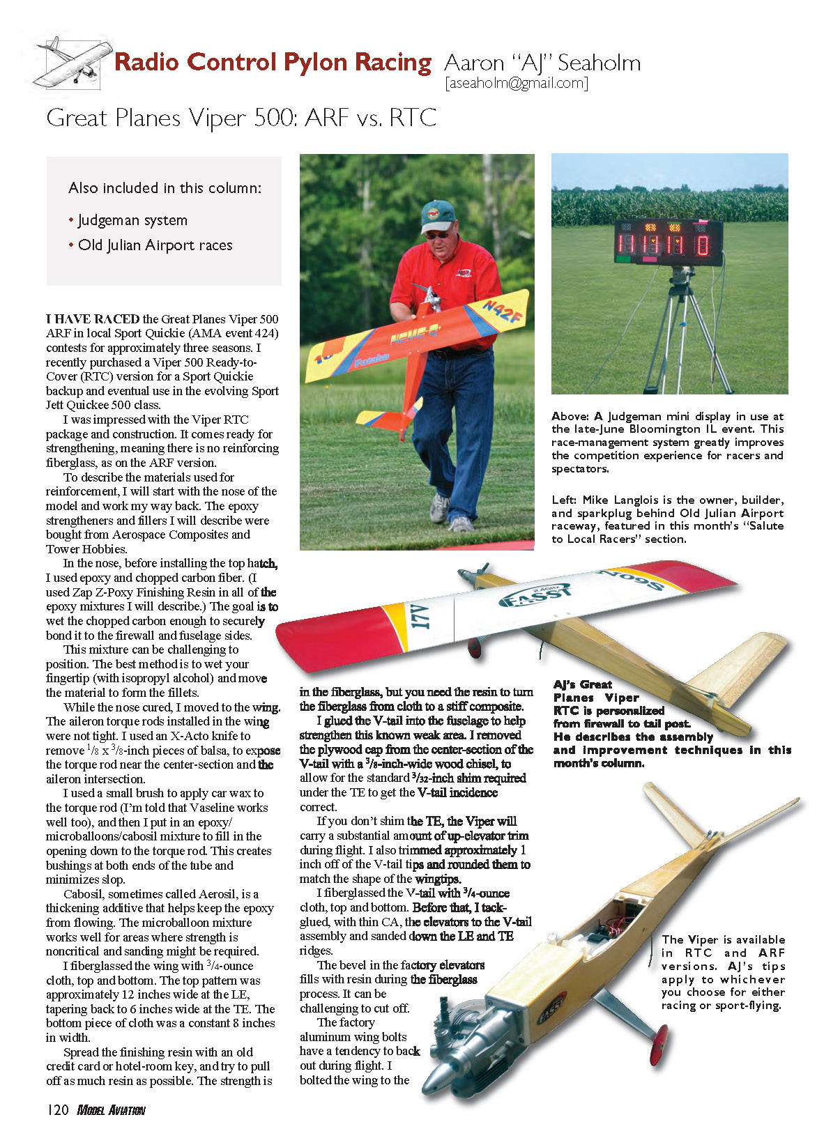
The Judgeman RC Pylon system is the brainchild of Hank Kauffman of Canada. Jim Allen, Tom Scott, Stan Douglass, Hank, and others have invested huge amounts of time designing and refining this system.
The simplest description for the Judgeman is a race-management system that simplifies officiating for the course worker. The digital displays and laptop computer are connected by a 2.4 GHz wireless signal.
Kansas City Radio Control (KCRC) purchased an assembled system from Tom Scott and the Can-Am Pylon Society in the winter of 2009. The KCRC system has boxes for the Pylon 1/2/3 judges that allow for quick cut signaling with the flip of a switch.
A large display for pilots and callers makes it easy to determine which lap it is, whether a cut has been posted and where, and it provides a consistent start-up and takeoff sequence for the start of a heat.
The small displays allow lap counters to see that their laps have registered and the crowd to see all the details of a heat. The Judgeman system tremendously improves the racing and spectator experience.
Salute to Local Racers
The first Pylon race of 2010 was held at Old Julian Airport raceway in Julian, North Carolina, May 1–2. By all accounts it was a huge success, thanks to the organization and dedication of the facility owner and builder, Mike Langlois.
He has set up a first-class operation with golf carts and a tractor-trailer to carry racers, callers, and aircraft to and from the flightline. Everything ran like clockwork as a result of exceptional planning and organization.
Several racers made the trek from across the country, with participants from as far away as California, Maryland, Tennessee, and Florida.
Event staff and course workers did a great job and withstood the effects of the heat to hold a well-run event. All course-worker positions were well equipped with sun shading and safety barriers. Safety is a primary focus during an RC Pylon event, and Mike’s attention to this was apparent.
Food and refreshments were available both days, handled by Mabel Langlois and her fine groups of cooks and preparers. Saturday night was especially nice; Mabel served North Carolina barbecue, which the racers ate under the shade of old pecan trees near the pit area.
This exceptional meal provided time for racers and workers to wind down, make new friends, and recap after an exciting day of competition. Good times, good food, and great racing are the essence of RC Pylon.
If you are ever in North Carolina, check out the Old Julian Airport or make plans to attend the next event that will be held there.
Sources
- Great Planes: (800) 637-7660 — www.greatplanes.com
- Aerospace Composites: (925) 443-5900 — www.acp-composites.com
- Tower Hobbies: (800) 637-6050 — www.towerhobbies.com
- ZAP: www.zapglue.com
- Old Julian Airport: www.oldjulianairport.com
- National Miniature Pylon Racing Association: www.nmpra.org
Transcribed from original scans by AI. Minor OCR errors may remain.

