
Radio Control Scale Aerobatics
John Glezellis [email protected]
Throwing your airplane around takes the right setup
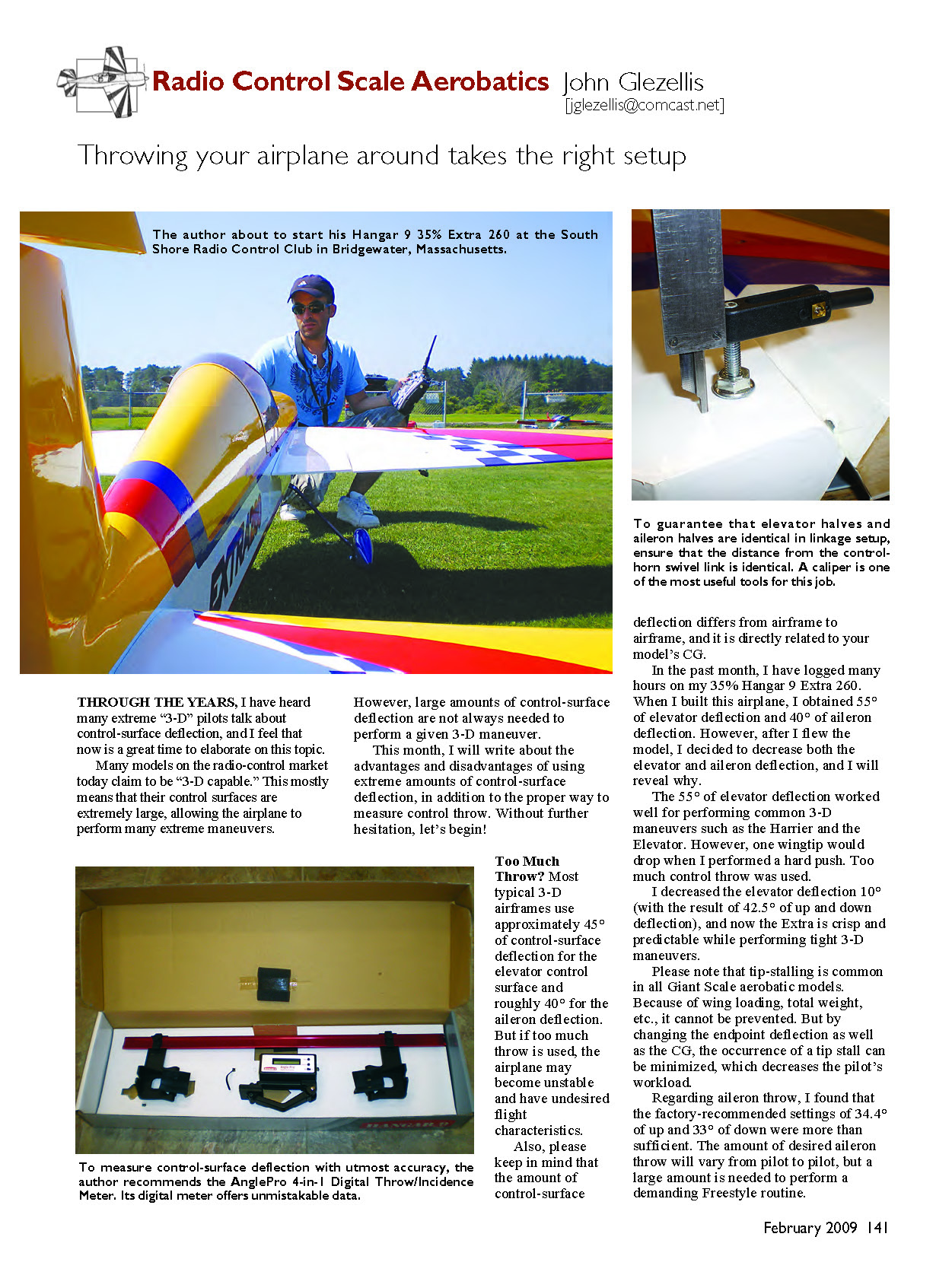
Through the years, I have heard many extreme "3-D" pilots talk about control-surface deflection, and I feel that now is a great time to elaborate on this topic.
Many models on the radio-control market today claim to be "3-D capable." This mostly means that their control surfaces are extremely large, allowing the airplane to perform many extreme maneuvers. However, large amounts of control-surface deflection are not always needed to perform a given 3-D maneuver.
This month I will write about the advantages and disadvantages of using extreme amounts of control-surface deflection, in addition to the proper way to measure control throw. Without further hesitation, let's begin!
Too Much Throw?
Most typical 3-D airframes use approximately 45° of elevator deflection and roughly 40° of aileron deflection. But if too much throw is used, the airplane may become unstable and exhibit undesired flight characteristics.
Also, please keep in mind that the amount of control-surface deflection differs from airframe to airframe and is directly related to your model's CG.
In the past month I logged many hours on my 35% Hangar 9 Extra 260. When I built this airplane, I obtained 55° of elevator deflection and 40° of aileron deflection. However, after I flew the model I decided to decrease both the elevator and aileron deflection, and I will explain why.
The 55° of elevator deflection worked well for performing common 3-D maneuvers such as the Harrier and the Elevator. However, one wingtip would drop when I performed a hard push. Too much control throw was being used. I decreased the elevator deflection 10° (resulting in 45° of up and down deflection), and now the Extra is crisp and predictable while performing tight 3-D maneuvers.
Please note that tip-stalling is common in all giant-scale aerobatic models. Because of wing loading, total weight, etc., it cannot be completely prevented. But by changing endpoint deflection as well as the CG, the occurrence of a tip stall can be minimized, which decreases the pilot's workload.
Regarding aileron throw, I found that the factory-recommended settings of 34.4° up and 33° down were more than sufficient. The amount of desired aileron throw will vary from pilot to pilot, but a large amount is needed to perform a demanding freestyle routine.
If needed, access the ATV (adjustable travel volume) screen on your computer radio and make the necessary adjustments. To obtain the best resolution out of your servos, it is best to have ATV values that are close to maximum.
Matching Elevator Halves
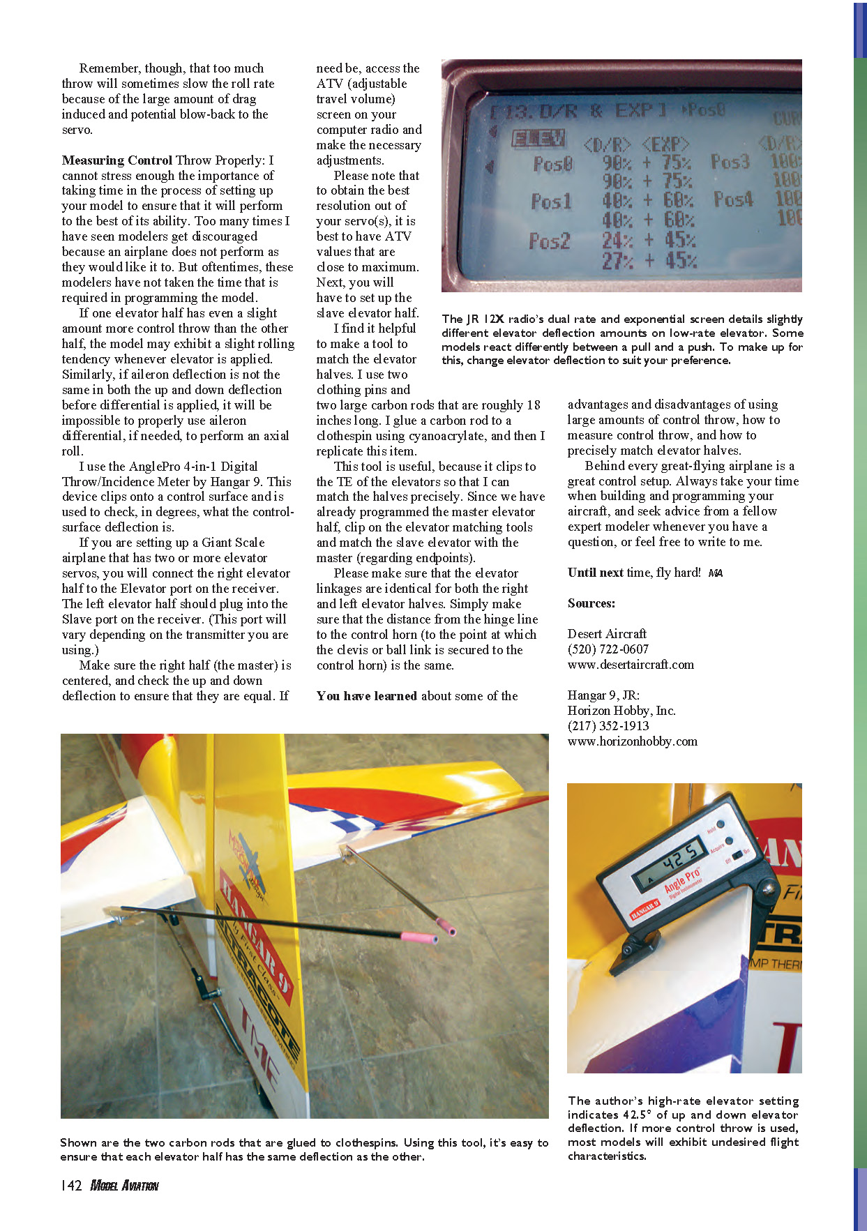
Next you will have to set up the slave elevator half. I find it helpful to make a simple tool to match the elevator halves precisely. I use two clothespins and two large carbon rods roughly 18 inches long. I glue a carbon rod to a clothespin using cyanoacrylate, and then I replicate that item.
This tool is useful because it clips to the trailing edge of the elevators so that I can match the halves precisely. Since we have already programmed the master elevator half, clip on the elevator-matching tools and match the slave elevator with the master regarding endpoints.
Please make sure that the elevator linkages are identical for both the right and left elevator halves. Ensure that the distance from the hinge line to the control horn (to the point at which the clevis or ball link is secured to the control horn) is the same on both sides.
Measuring Control Throw Properly
I cannot stress enough the importance of taking time during the setup of your model to ensure that it will perform to the best of its ability. Too many times I have seen modelers get discouraged because an airplane does not perform as they would like. Often, these modelers have not taken the time to properly measure and set control throws, end points, dual rates, mixes, and CG.
A good process for measuring control throw:
- Center the radio and servos, and set the control surfaces neutral.
- Measure deflection from neutral to maximum up and neutral to maximum down. You can measure in degrees (using a protractor held at the hinge line) or in millimeters/inches at a fixed distance from the hinge (for example, trailing-edge deflection at 12 inches out).
- Record both up and down values; symmetric throws are generally desirable unless a specific flight condition calls for asymmetry.
- Use the radio's ATV or endpoint adjustments to fine-tune travel and to ensure you are not overdriving the control surface past its safe mechanical limits.
- Fly with conservative throws first, then increase as needed for the maneuvers you plan to perform. Adjust CG and endpoints to minimize tip-stalling and to improve predictability.
You have learned about some of the advantages and disadvantages of using large amounts of control throw, how to measure control throw, and how to precisely match elevator halves.
Behind every great-flying airplane is a great control setup. Always take your time when building and programming your aircraft, and seek advice from a fellow expert modeler whenever you have a question, or feel free to write to me.
Until next time, fly hard! MA
Sources:
- Desert Aircraft (520) 722-0607 www.desertaircraft.com
- Hangar 9, JR: Horizon Hobby, Inc. (217) 352-1913 www.horizonhobby.com
Transcribed from original scans by AI. Minor OCR errors may remain.

