
The fundamentals of control linkages
John Glezellis [[email protected]]
Also included in this column:
- The importance of being choosy
There is no doubt in my mind that behind every great pilot is a well-built model. In the past, I have given you building and flying tips alike. Although many great ARFs exist on the market today with a great amount of prefabrication, a few areas should never be overlooked.
This month, I will discuss two important building fundamentals: mounting control horns and keeping hardware and radio equipment constant.
Control Horns
Some airplane manufacturers install control horns on their aircraft. This does save a fair amount of time. In the event that your model does not feature preinstalled control horns, I have some guidance to offer you.
I use threaded bolt-style control horns on all of my Giant Scale aircraft. If a kit does not come with control horns, I prefer to use 10-32 swivel clevis horns from Hangar 9.
That package comes with two swivel clevises, four 10-32 bolts, and two nuts. It supplies everything that is needed to complete the control horn section of the assembly for two control horn locations.
If you are flying a model that is 35% or larger, I advise you to use a 10-32 bolt for your control horns. If you use bolts that are too small, you may bend them in flight.
I have experimented with 8-32 bolts for the control horns on one of my 37% airplanes. They worked for the first few flights, but I soon found that the model would not trim out on the aileron surface. After I landed the aircraft, I saw that all six aileron control horn bolts were bent. Without further delay, I replaced them with 10-32 hardware.
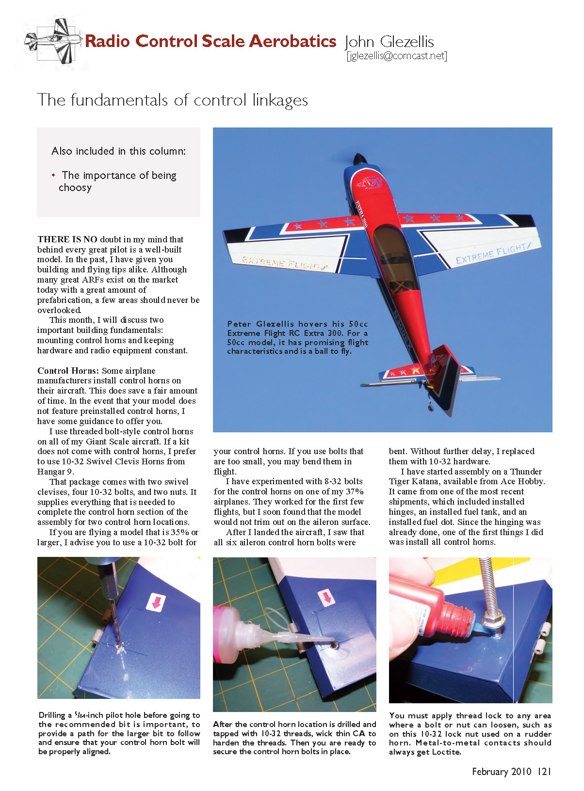
I have started assembly on a Thunder Tiger Katana, available from Ace Hobby. It came from one of the most recent shipments, which included installed hinges, an installed fuel tank, and an installed fuel dot. Since the hinging was already done, one of the first things I did was install all control horns.
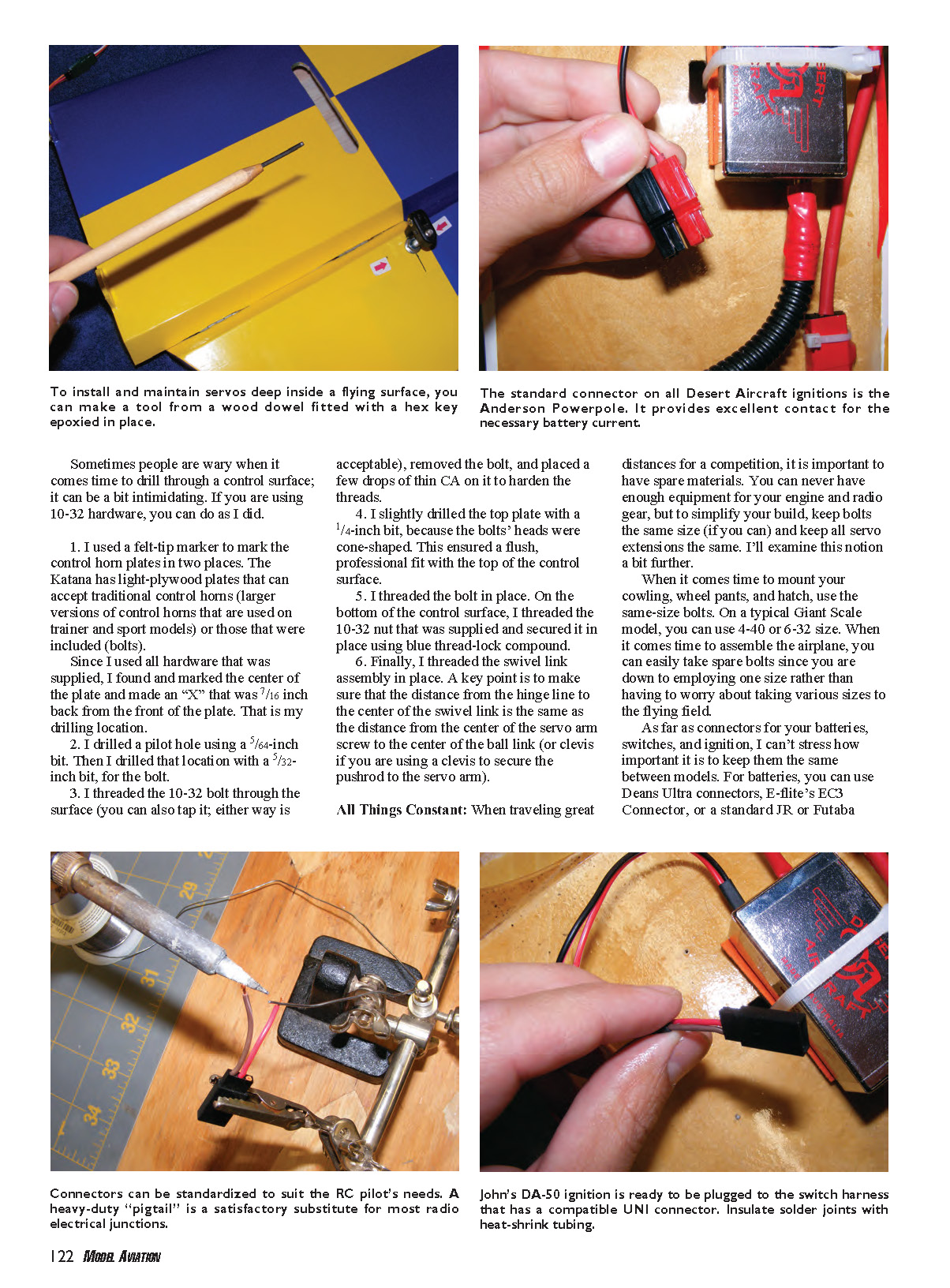
To install and maintain servos deep inside a flying surface, you can make a tool from a wood dowel fitted with a hex key epoxied in place.
The standard connector on many Desert Aircraft ignitions is the Anderson Powerpole. It provides excellent contact for the necessary battery current. Connectors can be standardized to suit the RC pilot’s needs. A heavy-duty "pigtail" is a satisfactory substitute for most radio electrical junctions. My DA-50 ignition is ready to be plugged into the switch harness that has a compatible UNI connector. Insulate solder joints with heat-shrink tubing.
Sometimes people are wary when it comes time to drill through a control surface; it can be a bit intimidating. If you are using 10-32 hardware, you can do as I did:
- I used a felt-tip marker to mark the control horn plates in two places. The Katana has light-plywood plates that can accept traditional control horns (larger versions of control horns that are used on trainer and sport models) or those that were included (bolts). Since I used all hardware that was supplied, I found and marked the center of the plate and made an "X" that was 7/16 inch back from the front of the plate. That is my drilling location.
- I drilled a pilot hole using a 5/64-inch bit. Then I drilled that location with a 5/32-inch bit for the bolt.
- I threaded the 10-32 bolt through the surface (you can also tap it; either way is acceptable), removed the bolt, and placed a few drops of thin CA on it to harden the threads.
- I slightly drilled the top plate with a 1/4-inch bit, because the bolts' heads were cone-shaped. This ensured a flush, professional fit with the top of the control surface.
- I threaded the bolt in place. On the bottom of the control surface, I threaded the supplied 10-32 nut and secured it in place using blue thread-lock compound.
- Finally, I threaded the swivel link assembly in place. A key point is to make sure that the distance from the hinge line to the center of the swivel link is the same as the distance from the center of the servo arm screw to the center of the ball link (or clevis if you are using a clevis to secure the pushrod to the servo arm).
All Things Constant
When traveling great distances for a competition, it is important to have spare materials. You can never have enough equipment for your engine and radio gear, but to simplify your build, keep bolts the same size (if you can) and keep all servo extensions the same. I'll examine this notion a bit further.
When it comes time to mount your cowling, wheel pants, and hatch, use the same-size bolts. On a typical Giant Scale model, you can use 4-40 or 6-32 size. When it comes time to assemble the airplane, you can easily take spare bolts since you are down to employing one size rather than having to worry about taking various sizes to the flying field.
As far as connectors for your batteries, switches, and ignition, I can't stress how important it is to keep them the same between models. For batteries, you can use Deans Ultra connectors, E-flite's EC3 connector, or a standard JR or Futaba connector.
I like the EC3 and Deans Ultra because they can handle higher amounts of current. The EC3 can handle up to 60 continuous amps and the Deans Ultra can handle 50 continuous amps.
I've been using the EC3 because that is what the JR and Spektrum batteries come pre-soldered with for either the Spektrum or JR VR6010 voltage regulators and PowerSafe receivers. However, all of that can be changed. I have seen modelers use Deans Ultra connectors off of their VR6010 regulators instead, because they have heavy-duty switches that are soldered with Deans Ultra connectors.
In addition, I have always replaced the connector that comes with a Desert Aircraft ignition with a standard female Futaba or JR heavy-duty lead. I do this as the lead plugs into a heavy-duty switch that has a male lead. Consistency is the key, and it will guarantee peace of mind when it comes time to replace the ignition or switch.
Always take time when it comes to key areas in building your Giant Scale Aerobatics models. As Murphy's Law states, "Anything that can go wrong will go wrong."
When things do go wrong, keeping things consistent between airframes will ensure peace of mind and success at the field. After all, you should be thinking about your next flying sequence — not changing connectors at the field.
Until next time, fly hard! JG
Sources
- Hangar 9
(800) 338-4639 www.hangar-9.com
- Thunder Tiger / Ace Hobby
(949) 900-3300 www.acehobby.com
- W.S. Deans Co.
(714) 828-6494 www.wsdeans.com
- E-flite
(800) 338-4639 www.e-flite.com
- Desert Aircraft
(520) 722-0607 www.desertaircraft.com
- JR
(800) 338-4639 www.jrradios.com
- Futaba
(800) 637-7660 www.futaba-rc.com
- Spektrum
(800) 338-4639 www.spektrumrc.com
- Extreme Flight RC
(770) 887-1794 www.extremeflightrc.com
- International Miniature Aerobatics Club
Transcribed from original scans by AI. Minor OCR errors may remain.

