
Radio Control Scale Aerobatics
John Glezellis [[email protected]]
Make the right choices for your Scale Aerobatics model
Also included in this column:
- How many servos your airplane needs
- Custom-fit servo mounts
- Switch-mounting tip
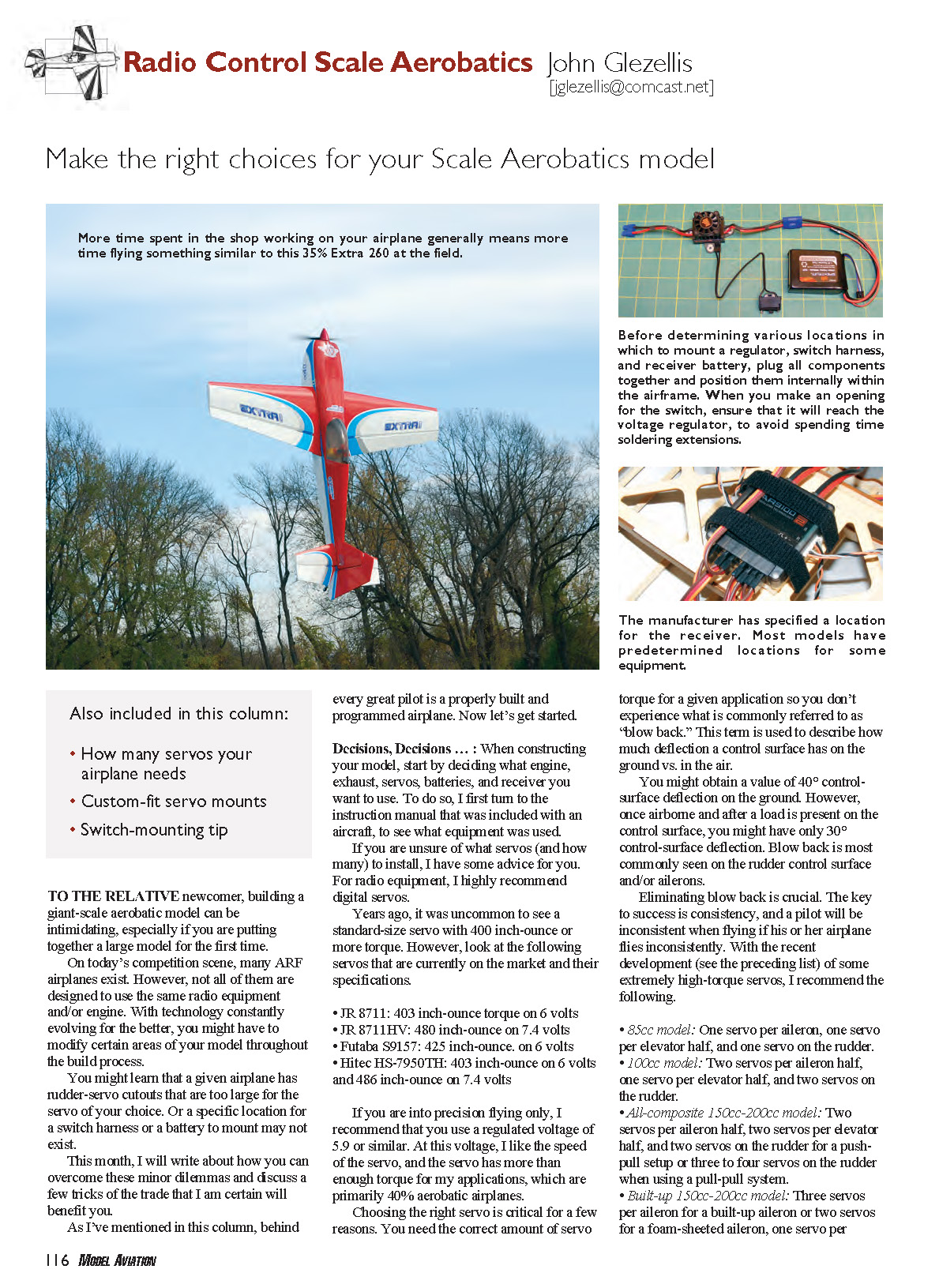
To the relative newcomer, building a giant-scale aerobatic model can be intimidating, especially if you are putting together a large model for the first time.
On today’s competition scene, many ARF airplanes exist. However, not all of them are designed to use the same radio equipment and/or engine. With technology constantly evolving for the better, you might have to modify certain areas of your model throughout the build process.
You might learn that a given airplane has rudder-servo cutouts that are too large for the servo of your choice, or that a specific location for a switch harness or a battery to mount may not exist.
This month, I will write about how you can overcome these minor dilemmas and discuss a few tricks of the trade that I am certain will benefit you.
As I’ve mentioned in this column, behind every great pilot is a properly built and programmed airplane. Now let’s get started.
Decisions, Decisions
When constructing your model, start by deciding what engine, exhaust, servos, batteries, and receiver you want to use. To do so, I first turn to the instruction manual that was included with an aircraft to see what equipment was used.
If you are unsure of what servos (and how many) to install, I have some advice for you. For radio equipment, I highly recommend digital servos.
Years ago, it was uncommon to see a standard-size servo with 400 inch-ounce or more torque. However, look at the following servos that are currently on the market and their specifications:
- JR 8711: 403 inch-ounce torque on 6 volts
- JR 8711HV: 480 inch-ounce on 7.4 volts
- Futaba S9157: 425 inch-ounce on 6 volts
- Hitec HS-7950TH: 403 inch-ounce on 6 volts and 486 inch-ounce on 7.4 volts
If you are into precision flying only, I recommend that you use a regulated voltage of 5.9 volts or similar. At this voltage, I like the speed of the servo, and the servo has more than enough torque for my applications, which are primarily 40% aerobatic airplanes.
Choosing the right servo is critical for a few reasons. You need the correct amount of servo torque for a given application so you don’t experience what is commonly referred to as "blow back." This term is used to describe how much deflection a control surface has on the ground vs. in the air.
You might obtain a value of 40° control-surface deflection on the ground. However, once airborne and after a load is present on the control surface, you might have only 30° control-surface deflection. Blow back is most commonly seen on the rudder control surface and/or ailerons.
Eliminating blow back is crucial. The key to success is consistency, and a pilot will be inconsistent when flying if his or her airplane flies inconsistently.
With the recent development of some extremely high-torque servos, I recommend the following:
- 85cc model: One servo per aileron, one servo per elevator half, and one servo on the rudder.
- 100cc model: Two servos per aileron half, one servo per elevator half, and two servos on the rudder.
- All-composite 150cc–200cc model: Two servos per aileron half, two servos per elevator half, and two servos on the rudder for a push-pull setup, or three to four servos on the rudder when using a pull-pull system.
- Built-up 150cc–200cc model: Three servos per aileron for a built-up aileron or two servos for a foam-sheeted aileron, one servo per elevator half, and two servos on the rudder for a push-pull setup, or three to four servos on the rudder when using a pull-pull system.
It is important to not only choose a servo with the proper amount of torque, but also to choose a servo that centers properly and has a good gear train. If your servo doesn't center properly, make sure that the linkage to which it is attached can move freely.
If any binding exists, try to find the source of the problem. If no binding exists and the servo still does not center properly, send it to the manufacturer to be serviced.
In the past I have experimented with a few servos from various manufacturers. All in all, I was most impressed with the centering of the JR 8711 and 8711HV.
In the ARFs I have built, all wing and tail surfaces have been designed for standard-size servos. However, not all rudder setups are designed for standard-size servos.
Some airplanes that were designed a few years ago might be set up for servos that are in the 1/4-scale size category or larger. Those have been replaced with much higher-torque servos that are much smaller in size, but they were the best option during their time period.
Several of those models are still in production, but manufacturers don't always keep up with modern technology. If your aircraft needs to be modified to accept smaller servos, don't worry.
Following is a step-by-step description of what I did on my 35% Katana to make it accept JR 8711 servos on an existing rudder tray that was made for larger servos.
- Measure the length of the servo opening and compare it to the servo.
- On light plywood that is the same thickness as the rudder servo tray, use a pencil to mark the length of the difference noted in step 1.
- Measure the width of the servo opening in the rudder servo tray. Mark this measurement on the piece of light plywood from step 2. Cut out this piece.
- Use medium CA to glue the piece of light plywood into the servo tray. Once finished, you will need to add a reinforcement piece of 1/8" light plywood to support the underside of the glue joint.
- Cut a strip of 1/8" light plywood that measures about 1 inch in width and roughly 3 inches in length.
- Glue the reinforcement strip from step 5 on the underside of the rudder tray. Center the rudder servo in the opening and drill 1/16-inch pilot holes so that it is ready to mount.
- Thread a servo screw in each hole, remove it, and apply a drop of thin CA to harden the threads.
- Repeat the preceding step for the other servos.
Measure Twice; Cut Once
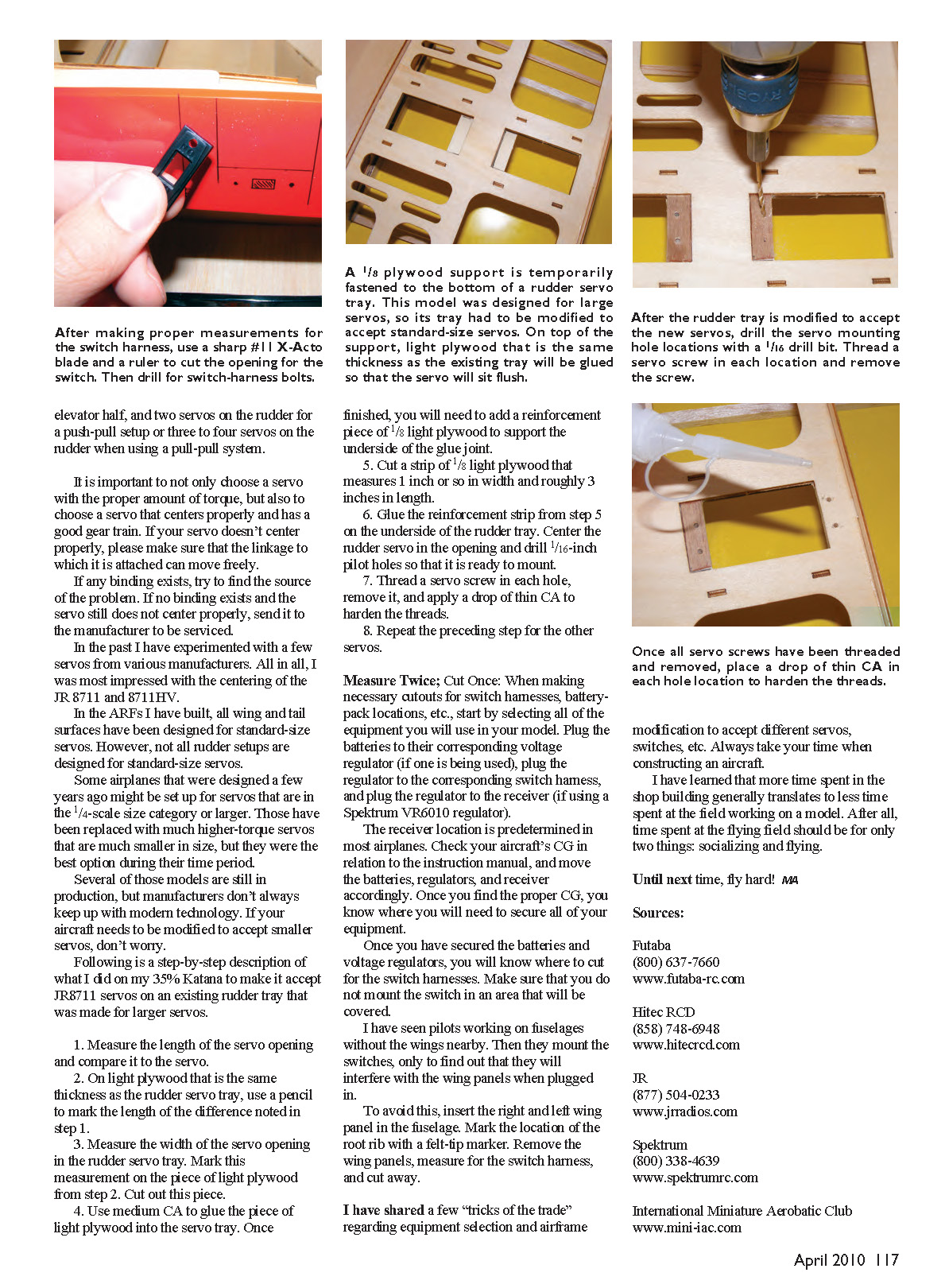
When making necessary cutouts for switch harnesses, battery-pack locations, etc., start by selecting all of the equipment you will use in your model. Plug the batteries to their corresponding voltage regulator (if one is being used), plug the regulator to the corresponding switch harness, and plug the regulator to the receiver (if using a Spektrum VR6010 regulator).
The receiver location is predetermined in most airplanes. Check your aircraft's CG in relation to the instruction manual, and move the batteries, regulators, and receiver accordingly. Once you find the proper CG, you will know where you will need to secure all of your equipment.
Once you have secured the batteries and voltage regulators, you will know where to cut for the switch harnesses. Make sure that you do not mount the switch in an area that will be covered.
I have seen pilots working on fuselages without the wings nearby, then they mount the switches only to find out that they will interfere with the wing panels when plugged in. To avoid this, insert the right and left wing panels in the fuselage. Mark the location of the root rib with a felt-tip marker. Remove the wing panels, measure for the switch harness, and cut away.
I have shared a few "tricks of the trade" regarding equipment selection and airframe modification to accept different servos, switches, etc. Always take your time when constructing an aircraft.
I have learned that more time spent in the shop building generally translates to less time spent at the field working on a model. After all, time spent at the flying field should be for only two things: socializing and flying.
Until next time, fly hard! JG
Sources:
- Futaba (800) 637-7660 www.futaba-rc.com
- Hitec RCD (858) 748-6948 www.hitecrcd.com
- JR (877) 504-0233 www.jrradios.com
- Spektrum (800) 338-4639 www.spektrumrc.com
- International Miniature Aerobatic Club www.mini-iac.com
Transcribed from original scans by AI. Minor OCR errors may remain.

