
RADIO CONTROL SLOPE SOARING
Dave Garwood, 5 Birch Ln., Scotia NY 12302; E-mail: [email protected]
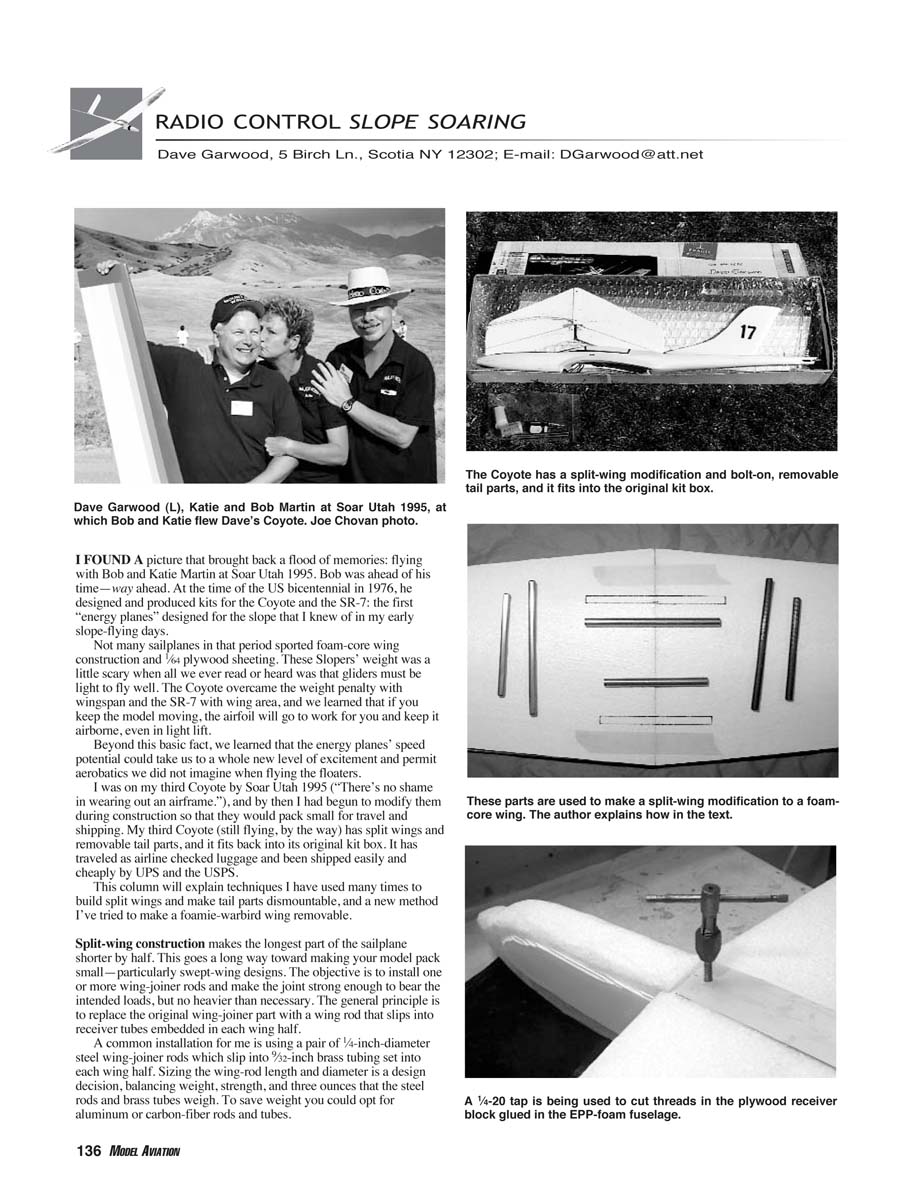
I found a picture that brought back a flood of memories: flying with Bob and Katie Martin at Soar Utah 1995. Bob was ahead of his time—way ahead. At the time of the U.S. bicentennial in 1976, he designed and produced kits for the Coyote and the SR-7: the first "energy planes" designed for the slope that I knew of in my early slope-flying days.
Not many sailplanes in that period sported foam-core wing construction and 1/64-inch plywood sheeting. These Slopers' weight was a little scary when all we ever read or heard was that gliders must be light to fly well. The Coyote overcame the weight penalty with wingspan and the SR-7 with wing area, and we learned that if you keep the model moving, the airfoil will go to work for you and keep it airborne, even in light lift.
Beyond this basic fact, we discovered that the energy planes' speed potential could take us to a whole new level of excitement and permit aerobatics we did not imagine when flying the floaters.
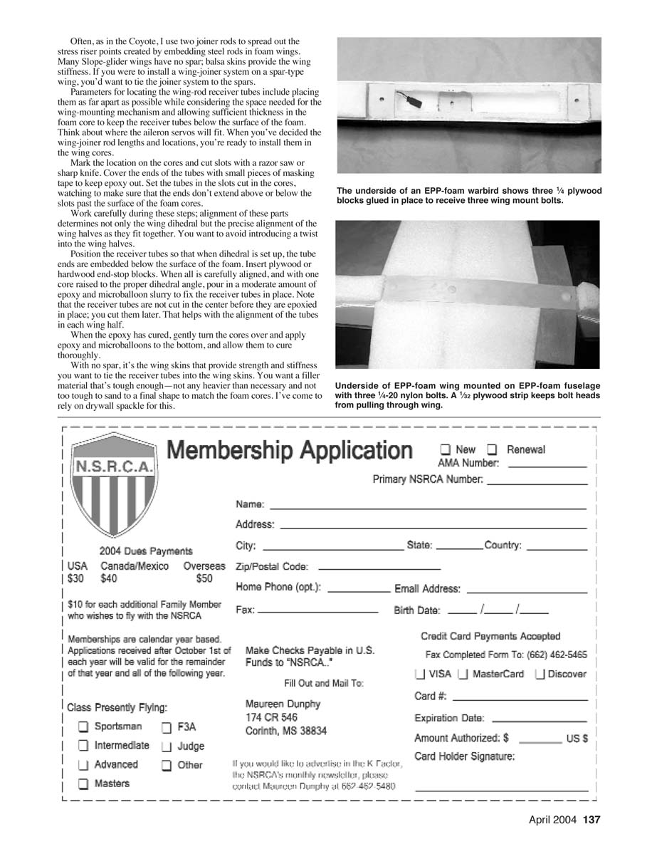
I was on my third Coyote by Soar Utah 1995 ("There's no shame in wearing out an airframe."), and by then I had begun to modify them during construction so that they would pack small for travel and shipping. My third Coyote (still flying, by the way) has split wings and removable tail parts, and it fits back into its original kit box. It has traveled as airline-checked luggage and been shipped easily and cheaply by UPS and the USPS.
This column explains techniques I have used many times to build split wings and make tail parts dismountable, and a method I’ve tried to make a foamie-warbird wing removable.
Why split wings and dismountable parts
- Split-wing construction makes the longest part of the sailplane shorter by half, which greatly reduces packing volume—especially for swept-wing designs.
- The objective is to install one or more wing-joiner rods and make the joint strong enough to bear intended loads, but no heavier than necessary.
- A dismountable tail and removable wing dramatically reduce the size of the shipping/packing box.
Split-wing construction: principles and hardware
- General principle: replace the original wing-joiner part with a wing rod that slips into receiver tubes embedded in each wing half.
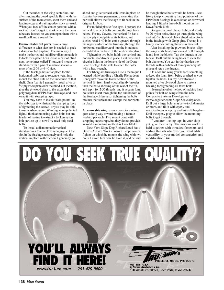
- Common installation: a pair of 1/4-inch-diameter steel wing-joiner rods that slip into 9/32-inch brass tubing set into each wing half.
- Trade-offs: choose rod length and diameter to balance weight and strength. To save weight you can use aluminum or carbon-fiber rods and tubes.
- On foam wings without a spar, use two joiner rods to spread stress-riser points created by embedded rods. If the wing has spars, tie the joiner system into the spars.
Locating and installing receiver tubes
- Decide tube locations: place them as far apart as possible while leaving room for the wing-mounting mechanism and aileron servos, and ensure sufficient foam thickness so the tubes sit below the surface.
- Mark the locations on the wing cores and cut slots with a razor saw or sharp knife.
- Cover tube ends with masking tape to keep epoxy out.
- Set the tubes in the slots, watching to make sure the tube ends don't extend above the surface of the foam cores.
- Align carefully—this determines wing dihedral and prevents introducing a twist into the wing halves.
- Position the receiver tubes so that when the dihedral is set, the tube ends are embedded below the foam surface. Insert plywood or hardwood end-stop blocks as needed.
- With one core raised to the proper dihedral angle, pour in a moderate amount of epoxy and microballoon slurry to fix the receiver tubes in place. Do not cut the tubes at the centerline before epoxying; cut them later to preserve alignment.
- After the epoxy cures, flip the cores and apply epoxy and microballoons to the bottom and allow to cure thoroughly.
Tying receiver tubes into the wing skins
- Without a spar, the skins provide the wing stiffness; tie the receiver tubes into the skins.
- Use a filler material that's tough enough, not excessively heavy, and sandable. I use drywall spackle for this.
- Cut the tubes at the wing centerline after the filler cures. Sand the cured spackle flush with the foam cores, sheet the wings, and add leading- and trailing-edge stock as usual.
- When you install a root rib at the center, mark where the brass tubes are so you can open them with a small drill and round file.
Dismountable tail parts
- Removable tail parts greatly reduce packing size.
- Horizontal stabilizer:
- Most common mount: install a pair of blind nuts (T-nuts) and secure the stabilizer with machine screws (commonly 2-56 or 4-40).
- On foamies: glue a 1/16- or 1/32-inch plywood plate over the blind-nut location, glue the plate to the EPP foam fuselage, and wrap with strapping tape.
- You may need hard points in the stabilizer for the clamping force; washers sometimes suffice. Nylon bolts are lighter but risk breaking; I’ve used steel bolts for reliability.
- Vertical stabilizer:
- On foamies many builders simply friction-fit vertically cut slots; I generally glue the fin in place since a permanent vertical still lets the fuselage fit in the kit box.
- On molded plastic fuselages: prepare the vertical to accept bolts from below. For my Coyote the vertical fin has a narrow plywood plate at its bottom; socket-head 4-40 bolts come upward through the fuselage, pass through the horizontal stabilizer, and thread into blind nuts embedded in the vertical fin.
- I cut two small circular holes in the lower side of the Duralene fuselage to reach the bolts with a hex wrench.
- For fiberglass fuselages: make the lower section of the vertical fin from hardwood slightly broader than the balsa sheeting, tap it for 2-56 threads, and accept long bolts that insert through the top and bottom of the fuselage. Tightening the bolts mounts the vertical and clamps the horizontal in place.
Removable wings for foam warbirds
- A removable one-piece wing makes a foamie warbird much more packable. Strapping-tape straps work but are less secure than bolted mounts.
- Example: Richard Loud mounts a Foam 51 slope-combat fighter wing with two bolts; he recommended three bolts to reduce the chance of ripping a hard point out of an EPP fuselage in a collision.
- My Kawafomaine Ki61 uses a three-bolt mount:
- Designed around inexpensive 1/4-20 nylon bolts that go through the wing and into 1/4-inch plywood plates glued into fuselage cutouts with Goop glue.
- After installing plywood blocks, align the wing in final position and drill through the wing into the blocks. Tap threads in the blocks and drill the wing holes to clear the bolt diameter.
- Harden threads by dribbling thin cyanoacrylate glue into the holes and retapping.
- On foamie wings, use a backing plate (e.g., 1/32-inch plywood) to keep the foam from crushing when tightening bolts.
Making hard points and using taps
- Another method: drill a large hole (about 3/8-inch diameter or more) and fill it with epoxy mixed with microballoons or epoxy and milled fiberglass. Drill the cured epoxy plug to allow the mounting bolts to pass.
- If you aren't using taps yet, give them a try. Adding threaded fasteners where you want them adds versatility to model construction and modification—the modern world is held together with threaded fasteners.
Contact info repeated for reference: Dave Garwood, [email protected]
Transcribed from original scans by AI. Minor OCR errors may remain.

