

RADIO CONTROL SLOPE SOARING
Dave Garwood, 5 Birch Ln., Scotia NY 12302; E-mail: [email protected]
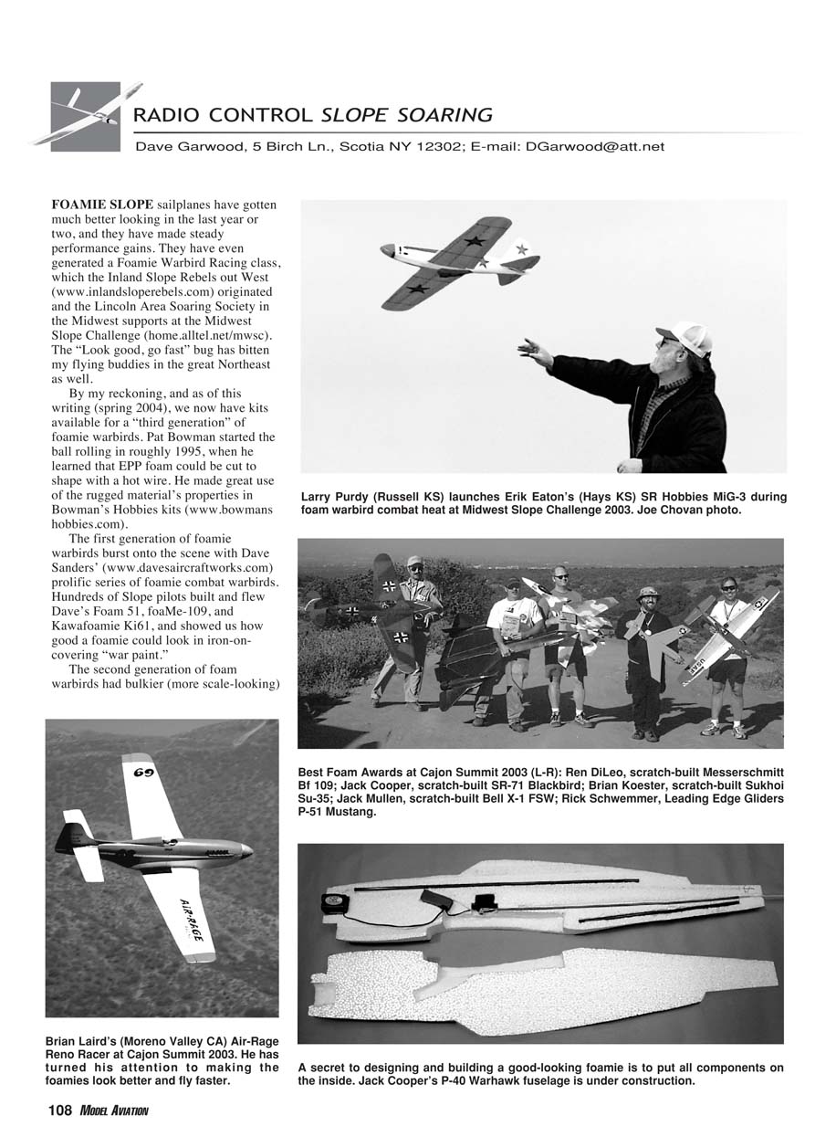
FOAMIE SLOPE sailplanes have gotten much better looking in the last year or two, and they have made steady performance gains. They have even generated a Foamie Warbird Racing class, which the Inland Slope Rebels out West (www.inlandsloperebels.com) originated and the Lincoln Area Soaring Society in the Midwest supports at the Midwest Slope Challenge (home.alltel.net/mwsc). The "look good, go fast" bug has bitten my flying buddies in the great Northeast as well.
By my reckoning, as of this writing (spring 2004), we now have kits available for a "third generation" of foamie warbirds. Pat Bowman started the ball rolling in roughly 1995, when he learned that EPP foam could be cut to shape with a hot wire. He made great use of the rugged material's properties in Bowman's Hobbies kits (www.bowmanshobbies.com).
The first generation of foamie warbirds burst onto the scene with Dave Sanders' prolific series of foamie combat warbirds. Hundreds of slope pilots built and flew Dave's Foam 51, Foam-109, and Kawafoamie Ki-61, and showed us how good a foamie could look in iron-on covering "war paint" (www.davesaircraftworks.com).
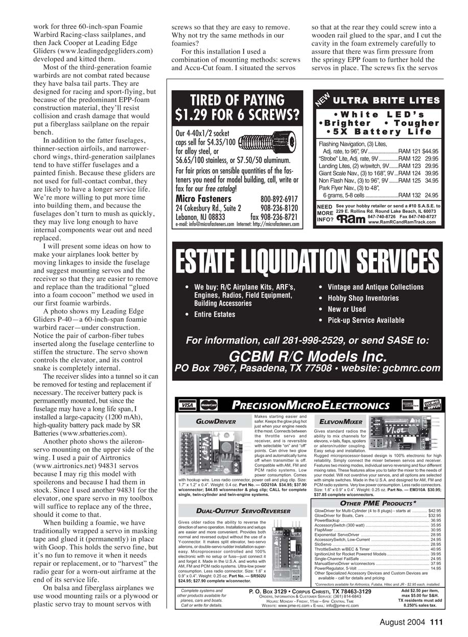
The second generation of foam warbirds had bulkier (more scale-looking) fuselages and thinner airfoils (less drag), and they were speedier. I saw Steve Patton's Focke-Wulf Ta 152 clocked at 109 mph in a dive at Cajon Summit. Steve's Messerschmitt Me 262 had the first really scale fuselage I remember seeing, along with his trademark thinner-section wing. Jack Cooper's Grumman Hellcat also had a fat fuselage—it truly looked the part—but still had a wide-chord wing, which gave plenty of lift but limited its top speed. Jack's Hellcat was the first kit I saw in which fuselage components disassembled to mount the internal components, and were then glued together for completion. Now we had all of the control linkages mounted internally for reduced parasitic drag and a smoother appearance.
Third-generation foamies
Then in May 2003 I saw and flew my first "third-generation" foamie: Brian Laird's original-design Air-Rage Reno Racer. There was a lot to like about that airplane. It had a fat fuselage and a thin, narrow-chord wing. Over the strapping tape was Solartex iron-on covering and a painted finish. I couldn't tell it was a foamie from more than a few feet away. It was heavy and flew fast, all the while tracking like it was on rails. Brian is perhaps the most prolific slope-soaring warbird designer in the country today, having produced maybe 20 designs in molded fiberglass with sheeted foamcore wings under the "Slope Scale" brand name (www.rcglider.com). It was a happy day for foamie fliers when Brian applied his talent and experience to foam—especially for those who wanted to fly fast and look good while doing it. He did the basic design work for three 60-inch-span Foamie Warbird Racing-class sailplanes, and then Jack Cooper at Leading Edge Gliders (www.leadingedgegliders.com) developed and kitted them.
Most of the third-generation foamie warbirds are not combat rated because they have balsa tail parts. They are designed for racing and sport flying, but because of the predominant EPP-foam construction material, they'll resist collision and crash damage that would put a fiberglass sailplane on the repair bench.
In addition to the fatter fuselages, thinner-section airfoils, and narrower-chord wings, third-generation sailplanes tend to have stiffer fuselages and a painted finish. Because these gliders are not used for full-contact combat, they are likely to have a longer service life. We're more willing to put more time into building them, and because the fuselages don't turn to mush as quickly, they may live long enough to have internal components wear out and need replaced.
I will present some ideas on how to make your airplanes look better by moving linkages to inside the fuselage and suggest mounting servos and the receiver so that they are easier to remove and replace than the traditional "glued into a foam cocoon" method we used in our first foamie warbirds.
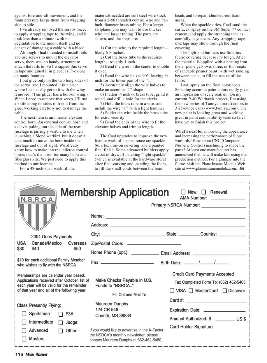
A photo shows my Leading Edge Gliders P-40—a 60-inch-span foamie warbird racer—under construction. Notice the pair of carbon-fiber tubes inserted along the fuselage centerline to stiffen the structure. The servo shown controls the elevator, and its control snake is completely internal.
The receiver slides into a tunnel so it can be removed for testing and replacement if necessary. The receiver battery pack is permanently mounted, but since the fuselage may have a long life span, I installed a large-capacity (1200 mAh), high-quality battery pack made by SR Batteries (www.srbatteries.com).
Another photo shows the aileron-servo mounting on the upper side of the wing. I used a pair of Airtronics (www.airtronics.net) 94831 servos because I may rig this model with spoilers and because I had them in stock. Since I used another 94831 for the elevator, one spare servo in my toolbox will suffice to replace any of the three, should it come to that.
Servo and receiver mounting
When building a foamie, we have traditionally wrapped a servo in masking tape and glued it (permanently) in place with Goop. This holds the servo fine, but it's no fun to remove it when it needs repair or replacement, or to "harvest" the radio gear for a worn-out airframe at the end of its service life.
On balsa and fiberglass airplanes we use wood mounting rails or a plywood or plastic servo tray to mount servos with screws so that they are easy to remove. Why not try the same methods in our foamies?
For this installation I used a combination of mounting methods: screws and Accu-Cut foam. I situated the servos so that at the rear they could screw into a wooden rail glued to the spar, and I cut the cavity in the foam extremely carefully to assure that there was firm pressure from the springy EPP foam to further hold the servos in place. The screws fix the servos so that they are mounted solidly and yet accessible for service or replacement. The foam pressure keeps them from wiggling side to side and resists fore-and-aft movement.
I've already removed the servos once, to apply strapping tape to the wing, and it took less than a minute, with no degradation to the mount itself and no danger of damaging a cable with a blade.
Although I had intended to install rails and use screws to mount the elevator servo, there was no handy structure to attach the rails to. So I wrapped this servo in tape and glued it in place, as I've done on many foamies. I put glue only on the two long sides of the servo, and I mounted it in a place where I can easily get to it with the wing removed. (This glider has a bolt-on wing.) When I need to remove that servo, I'll run a knife along its sides to free it from the glue, working carefully not to damage the cable.
Internal elevator control horn
An external control horn and a clevis poking out the side of the rear fuselage is jarringly visible to me when launching a slope warbird, but it doesn't take much to move the horn inside the fuselage and out of sight. We already know how to make internal aileron control horns; that's the norm for many balsa and fiberglass kits. We just need to apply this method to our foamies.
For a 48-inch-span warbird, the materials needed are soft steel wire stock from a 2-56 threaded control wire and 5/32-inch-diameter brass tubing. For a larger sailplane, you may want to use thicker wire and larger tubing. The parts are shown, and the steps are:
- Cut the wire to the required length—likely 6–8 inches.
- Cut the brass tube to the required length—roughly 1 inch.
- Bend the wire in the center to double it over.
- Bend the wire halves 90°, leaving 1/2 inch for the lower part of the "T."
- Accurately align the wire halves to make an accurate "T" shape.
- Flatten 1/4 inch of brass tube, grind it round, and drill a hole for the clevis.
- Hold the brass tube in a vise, and install the wire "T" with a light hammer.
- Solder the wire inside the brass tube for extra security.
- Bend the ends of the wire to fit the elevator halves and trim to length.
Finishing and covering
The final upgrades to improve the new foamie warbird's appearance are spackle, Solartex iron-on covering, and a painted final finish. Some advanced builders apply a coat of drywall-patching "light spackle" (available at the hardware store) after final carving and sanding of the foam, to fill the small voids between the foam beads and to repair chunked-out foam areas.
When the spackle dries, final-sand the surfaces, spray on 3M Super 77 contact cement, and apply the strapping tape as carefully as you can. Any strapping-tape overlaps may show through the final covering.
High-end builders use Solartex fabric covering because it's tough. After the material is applied with a heating iron, the airplane gets two, three, or four coats of sandable primer paint, with wet sanding between coats, to fill the weave of the fabric. Last, spray on the final color coats. Selecting accurate paint colors really gives an impression of scale realism. On my current P-40 Warhawk project, I'm using the new series of Tamiya aircraft colors in 3.25-ounce cans (www.tamiya.com). The new paint is looking great and working well in paint compatibility tests so far; I have yet to finish this project.
What's next?
What's next for improving the appearance and increasing the performance of slope warbirds? How about CNC (computer numeric control) machining to shape the parts? At least one manufacturer has announced that he will make kits using that production method. For a glimpse into the future, visit Plane Insane Models at www.planeinsanemodels.com.
Transcribed from original scans by AI. Minor OCR errors may remain.

