
Radio Control Slope Soaring
Dave Garwood [[email protected]]
Installing aileron control linkages
"It's what you learn after you know it all that really counts." I wish I could remember who taught me that. It may be from the writings of Dave Thornburg or perhaps spoken by one of the philosopher fliers I’ve had the good fortune to fly with and learn from.
I had intended to write this column detailing my method of installing aileron control linkages, thinking that since I had done it 70 or more times I had the routine down and would be able to bestow my wisdom on the readership—especially those with less time at the building bench.
But, alas and alack, my 71st aileron installation proved to have a crucial flaw. Following is the story of how the linkage was built and how the flaw was discovered and rectified.
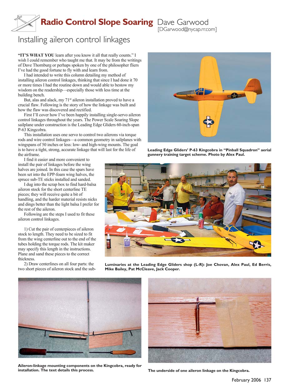
First I’ll cover how I’ve been happily installing single-servo aileron control linkages throughout the years. The Power Scale Soaring slope sailplane under construction is the Leading Edge Gliders 60-inch-span P-63 Kingcobra.
This installation uses one servo to control two ailerons via torque rods and wire control linkages—a common geometry in sailplanes with wingspans of 50 inches or less: low- and high-wing mounts. The goal is to have a tight, strong, accurate linkage that will last for the life of the airframe.
I find it easier and more convenient to install the pair of linkages before the wing halves are joined. In this case the spars have been set into the EPP-foam wing halves, the spruce sub-TE sticks installed and sanded.
I dug into the scrap box to find hard-balsa aileron stock for the short centerline TE pieces; they will receive quite a bit of handling, and the harder material resists nicks and dings better than the light balsa I prefer for the rest of the aileron.
Following are the steps I used to fit these aileron control linkages.
- Cut the pair of centerpieces of aileron stock to length. They need to be sized to fit from the wing centerline out to the end of the tubes holding the torque rods. The kit maker may specify this length in the instructions. Plane and sand these pieces to the correct thickness.
- Draw centerlines on all four parts: the two short pieces of aileron stock and the sub-TE and TE stock where the torque tubes will be located. These serve as guides to carve half-round slots in the sub-TE and in the TE stock to enclose the torque-rod holder tubes.
- Carve the half-round slots with a hobby knife or a roto-tool. Work slowly and carefully. If you use a knife, remember that a sharp blade is safer than a dull one; less pressure is needed to make the cut, reducing the hazard if the knife slips. Be sure to hold the part and the knife so that the knife will not cause injury if it does slip.
- Finish shaping the slots with a small round file, trial-fitting the parts often to see when the slots are just deep enough to fit in place with the torque-rod tubes inside.
- Final-shape and sand all four of the wing TE pieces: the short pieces to be mounted as TEs and the long pieces that will become ailerons. This includes end-to-end slot fit, tip-shaping, and overall surface sanding.
- Tape the ailerons in place. Working from the bottom, mark the location of the outer 90° bend in the aileron torque-rod linkage. Remove the ailerons and make a groove, with a medium round file, that is slightly larger than is needed for the wire alone.
- Fit short brass tubes, with inside diameters just large enough to allow the wire to slide freely. The tube provides long-term wear resistance and allows the aileron to move without binding or straining the aileron-control torque rod. For ailerons hinged at the top, the rod will slide substantially within the tube.
- Tape ailerons in their final installed location, with the control torque rod fitted, and place the wing halves inverted on the workbench. With a bit of tape sealing the TE of the brass tube to keep epoxy out, mount the tubes with a minimal amount of epoxy. I like to let the assemblies cure overnight at this point.
- The next day check the ailerons for free movement and clean up excess epoxy. With the ailerons separated from the wing halves, fill any gaps with epoxy and apply a piece of fiberglass cloth to strengthen and stiffen the inside end of the aileron and give a smooth surface for the iron-on covering. When cured, trim excess fiberglass cloth and sand the parts.
- Install the aileron servo and wire control links according to the kit manufacturer's instructions and/or your preference for hardware. I like hinging the ailerons with the covering film or fabric because it produces a highly flexible hinge with a long service life, and it stops air from circulating through the hinge line. I hinge scale airplanes on the top to produce a less-visible hinge line.
Using an Airtronics 94358 high-torque servo to swing the big ailerons, I hauled my new Kingcobra to Wilson Lake, Kansas, for sport flying and to run in the 2005 Midwest Slope Challenge Foamie Warbird Racing class.
We had excellent winds and good lift in the days before the 2005 event, and the Kingcobra's flight performance exceeded my expectations. Getting bolder with each passing hour, my model's climbs got higher and its dives got faster and longer.
Then—gadzooks!—aileron flutter! My heart sank.
Flutter is rapid and energetic oscillation of a control surface in the airstream. Once control-surface flutter starts, it tends to increase in severity, sometimes to the point where the aileron or elevator is ripped from the airframe. Suppressing control-surface flutter is a design consideration in models and in full-scale aircraft, and there are design techniques to reduce the chance that flutter will occur.
Once flutter is spotted (and sometimes it can be heard), it's important to reduce airspeed quickly, generally by pulling up into a climb, to stop the flutter and reduce the chances of airframe damage. If you're lucky and the model is still controllable, bring it in for a landing. Then search for the cause of the flutter and devise a strategy to eliminate it.
I asked the designer—Jack Cooper—to look at my aileron setup and see how it could be improved. He found two possible contributing factors and fixed them both.
There was a tiny bit of excessive clearance between the nylon threaded fittings on the torque rods and their mating clevises. That might be enough to contribute to flutter starting, but Jack looked further and decided that the wire control links between the servo arms and the torque rods were not stiff enough to handle the speeds at which I had been flying.
Jack stiffened the 1/16-inch-diameter wire control links by gluing carbon-fiber tubes in place with plastic-tube spacers between the carbon-fiber tubes and the wires. Good news: problem solved. Flying the 'cobra five more days, including one day with steady 28 mph winds gusting to 40, posed no more flutter problems.
Another way to stiffen the linkage using fewer parts might be to install heavier and stiffer wire for the control linkages. Rather than the 1/16-inch-diameter variety with 2-56 threads, use the next size heavier, with 4-40 threads.
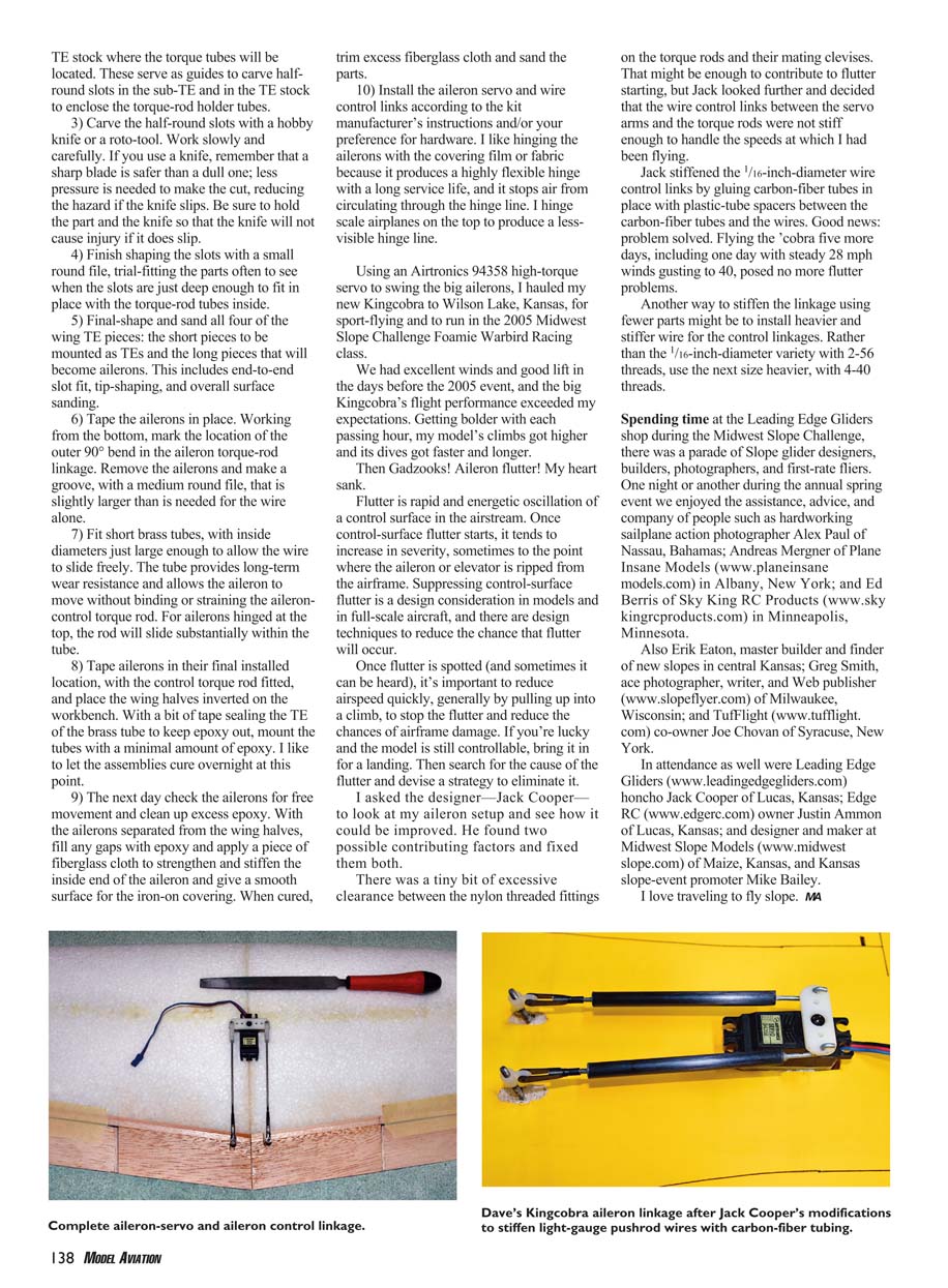
Spending time at the Leading Edge Gliders shop during the Midwest Slope Challenge, there was a parade of slope glider designers, builders, photographers, and first-rate fliers. One night or another during the annual spring event we enjoyed the assistance, advice, and company of people such as:
- Alex Paul, sailplane action photographer, Nassau, Bahamas
- Andreas Wenger, Plane Insane Models, Albany, New York (www.planeinsanemodels.com)
- Ed Berris, Sky King RC Products, Minneapolis, Minnesota (www.skykingrcproducts.com)
- Erik Eaton, master builder and finder of fine slopes in central Kansas
- Greg Smith, ace photographer, writer, and Web publisher, slopeflyer.com, Milwaukee, Wisconsin
- Joe Chovan, TutFlight co-owner, Syracuse, New York (www.tutflight.com)
- Jack Cooper, Leading Edge Gliders, Lucas, Kansas (www.leadingedgegliders.com)
- Justin Ammon, Edge RC owner, Lucas, Kansas (www.edgerc.com)
- Mike Bailey, designer and maker at Midwest Slope Models, Maize, Kansas, and Kansas slope-event promoter (www.midwestslope.com)
I love traveling to fly slope.
Transcribed from original scans by AI. Minor OCR errors may remain.

