
Radio Control Slope Soaring
Dave Garwood [[email protected]]
Foam-wing cracked-spar repair
I'm still repairing my favorite long-span slope cruiser: a Dave's Aircraft Works 120-inch-span Schleicher Ka-6E EPP foamie. It looks great in the sky, and it flies so smoothly.
You may remember it from a previous mention. I crashed it because it ran out of onboard electrical power — a "preventable" crash, which makes for greater gnashing of teeth and more colorful cussing during the postmortem review.
In addition to replacing the receiver battery pack, I needed to fix or replace three stripped servos and repair a cracked spar. Since you might have models that need similar repairs, I'll document the steps I used to get this well-loved sailplane back to flying condition.
It's not hard to diagnose a cracked spar: hold the wing tight to the bench and gently lift the tip. If, instead of flexing in a broad curve along the span, the flex is concentrated at a point, that point is where spar strength has failed or is otherwise compromised.
Start by removing the covering and the strapping tape to get a look at the wing's parts. Chances are you'll know in very few minutes where the fracture is.
The next step is to design a technique to restore the spar's strength. Keeping the weight of the repair low is a plus. For this Ka-6 fix, the method I used was to splint the spar with spruce, using wood pieces that extended 3 inches on either side of the break.
To have room to install the splints, remove some EPP foam with either a rotary tool or by hand with a blade and long-nose pliers. I used a Dremel rotary tool with a cylindrical steel cutter bit to hollow out a channel adjacent to the spar. Don't be afraid to dig in here; you'll make it smooth again later.
I shaped the splints to fit close to the spar and glued them in with polyurethane glue (Gorilla Glue and Elmer's Ultimate Polyurethane Glue are examples). That adhesive makes an incredibly strong bond between porous materials, and it expands slightly, helping to fill the space left from grinding out wing foam to get to the break.
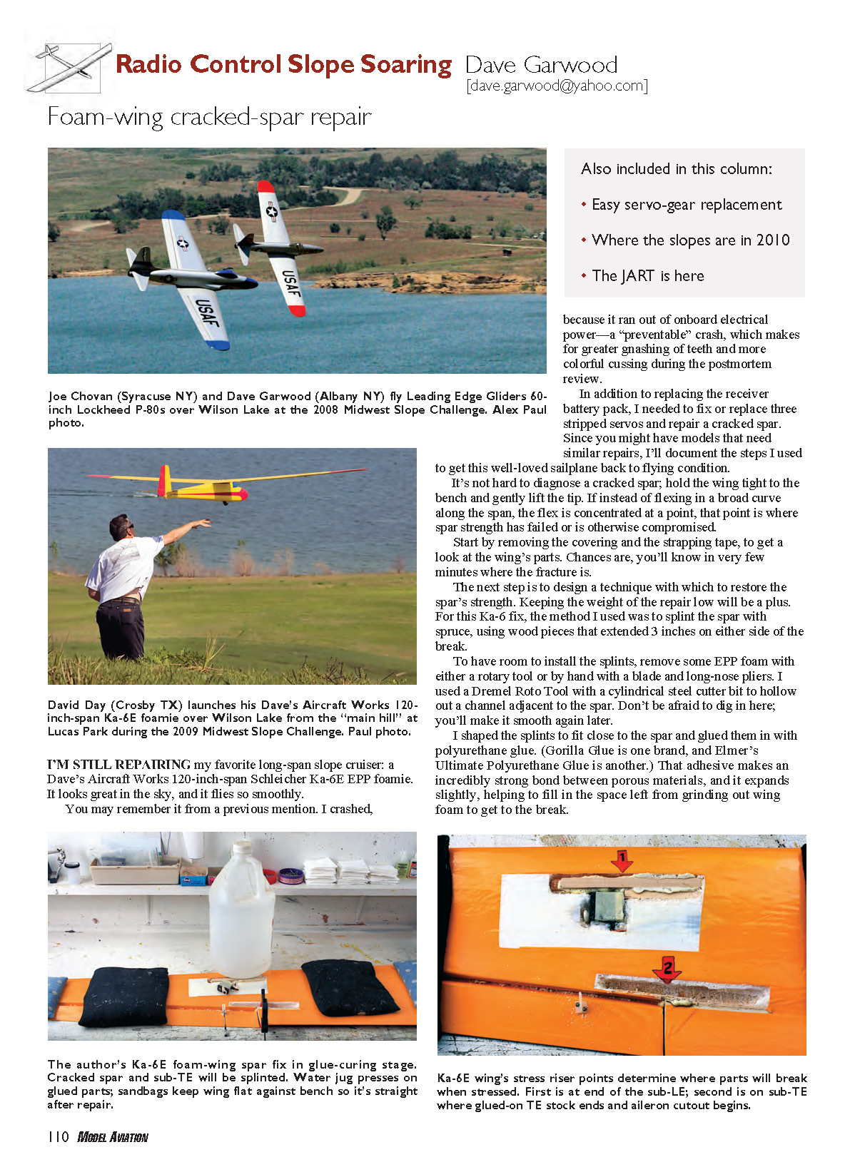
I let the glue joints cure overnight with the wing weighted and flat on the workbench. After using polyurethane glue, clean up with mineral spirits — in a properly ventilated area, of course. The next day, grind or sand off the excess glue and fill remaining cavities where necessary, using foaming glue or spackle.
In addition to the cracked spar I had a cracked sub-TE (sub trailing edge), so I cut another slot, fashioned another splint, and glued it in and let it cure during the second night. Finish by filling voids where they remain, re-taping and sanding smooth, and finally re-covering. The spar and sub-TE are now stronger than the originals at the fracture points, and the places where they will break in the next crash have been moved a few inches. That is because I moved the stress-riser points — the places where reinforcing strength ends suddenly — and that generally defines where the break point will be when the structure is overstressed.
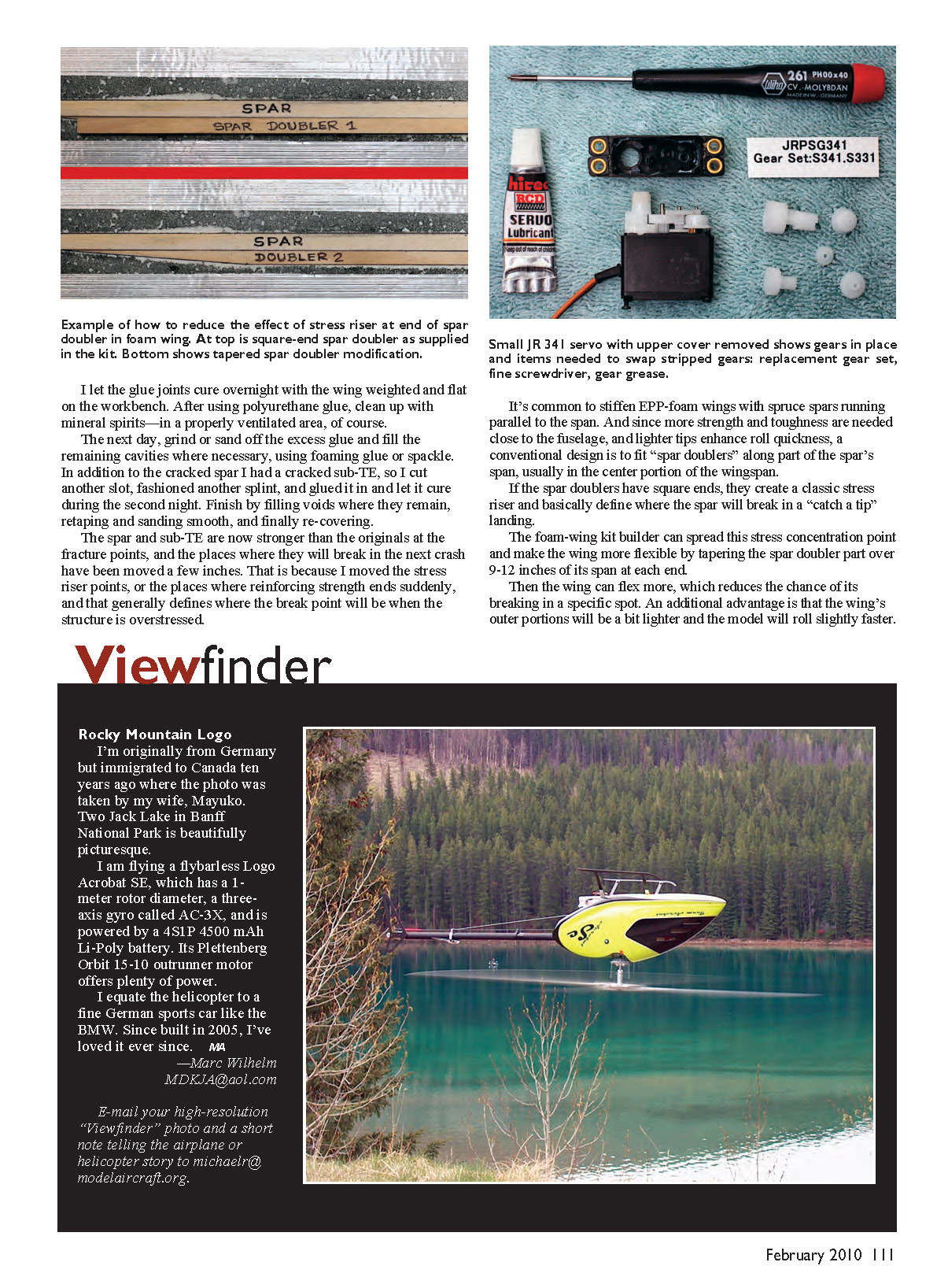
It's common to stiffen EPP-foam wings with spruce spars running parallel to the span. Since more strength and toughness are needed close to the fuselage and lighter tips enhance roll quickness, a conventional design is to fit "spar doublers" along part of the spar's span, usually in the center portion of the wingspan.
If the spar doublers have square ends, they create a classic stress riser and basically define where the spar will break in a "catch a tip" landing. The foam-wing kit builder can spread this stress concentration point and make the wing more flexible by tapering the spar-doubler part over 9–12 inches of its span at each end. Then the wing can flex more, which reduces the chance of its breaking in a specific spot. An additional advantage is that the wing’s outer portions will be a bit lighter and the model will roll slightly faster.
Stripped servo gears and repair
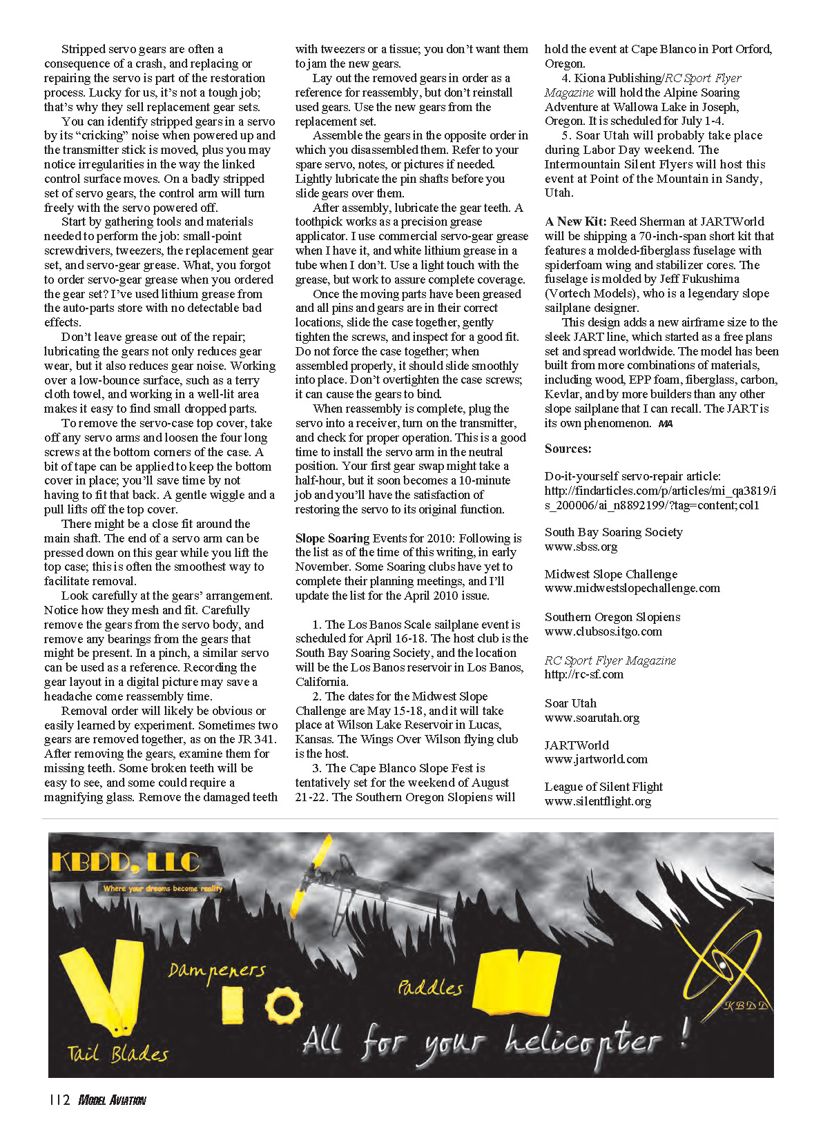
Stripped servo gears are often a consequence of a crash, and replacing or repairing the servo is part of the restoration process. Luckily, it’s not a tough job; that’s why replacement gear sets are sold.
You can identify stripped gears by a "cricking" noise when the servo is powered up and the transmitter stick is moved, and by irregularities in the way the linked control surface moves. On a badly stripped set, the control arm will turn freely with the servo powered off.
Start by gathering tools and materials: small-point screwdrivers, tweezers, the replacement gear set, and servo-gear grease. If you forgot to order servo-gear grease, white lithium grease from the auto-parts store works acceptably.
Don’t leave grease out of the repair; lubricating the gears reduces gear wear and gear noise. Work over a low-bounce surface such as a terry-cloth towel and in a well-lit area to make it easy to find small dropped parts.
To remove the servo-case top cover, take off any servo arms and loosen the four long screws at the bottom corners of the case. A bit of tape can be applied to keep the bottom cover in place; you’ll save time by not having to fit that back. A gentle wiggle and pull lifts off the top cover.
There might be a close fit around the main shaft. The end of a servo arm can be pressed down on this gear while you lift the top case; this is often the smoothest way to facilitate removal.
Look carefully at the gears’ arrangement. Notice how they mesh and fit. Carefully remove the gears from the servo body, and remove any bearings from the gears that might be present. In a pinch, a similar servo can be used as a reference. Recording the gear layout in a digital picture may save a headache at reassembly.
Removal order will likely be obvious or easily learned by experiment. Sometimes two gears are removed together, as on the JR 341. After removing the gears, examine them for missing teeth. Some broken teeth are easy to see; others may require a magnifying glass. Remove the damaged teeth with tweezers or a tissue; you don’t want them to jam the new gears.
Lay out the removed gears in order as a reference for reassembly, but don’t reinstall used gears. Use the new gears from the replacement set.
Assemble the gears in the opposite order in which you disassembled them. Refer to your spare servo, notes, or pictures if needed. Lightly lubricate the pin shafts before you slide gears over them.
After assembly, lubricate the gear teeth. A toothpick works as a precision grease applicator. Use a light touch but assure complete coverage.
Once the moving parts have been greased and all pins and gears are in their correct locations, slide the case together, gently tighten the screws, and inspect for a good fit. Do not force the case together; when assembled properly, it should slide smoothly into place. Don’t overtighten the case screws; it can cause the gears to bind.
When reassembly is complete, plug the servo into a receiver, turn on the transmitter, and check for proper operation. This is a good time to install the servo arm in the neutral position. Your first gear swap might take a half-hour, but it soon becomes a 10-minute job and you'll have the satisfaction of restoring the servo to its original function.
Slope Soaring Events for 2010:
Following is the list as of the time of this writing, in early November. Some soaring clubs have yet to complete their planning meetings, and I’ll update the list for the April 2010 issue.
- The Los Banos Scale Sailplane event — April 16–18
- Host: South Bay Soaring Society
- Location: Los Banos Reservoir, Los Banos, California
- Midwest Slope Challenge — May 15–18
- Host: Wings Over Wilson flying club
- Location: Wilson Lake Reservoir, Lucas, Kansas
- Cape Blanco Slope Fest — tentatively August 21–22
- Host: Southern Oregon Slopians
- Location: Cape Blanco, Port Orford, Oregon
- Alpine Soaring Adventure — July 1–4
- Host: Kiona Publishing / RC Sport Flyer Magazine
- Location: Wallowa Lake, Joseph, Oregon
- Soar Utah — probable during Labor Day weekend
- Host: Intermountain Silent Flyers
- Location: Point of the Mountain, Sandy, Utah
A New Kit
Reed Sherman at JARTWorld will be shipping a 70-inch-span short kit that features a molded-fiberglass fuselage with spiderfoam wing and stabilizer cores. The fuselage is molded by Jeff Fukushima (Vortech Models), who is a legendary slope sailplane designer.
This design adds a new airframe size to the sleek JART line, which started as a free-plans set and spread worldwide. The model has been built from more combinations of materials — including wood, EPP foam, fiberglass, carbon, and Kevlar — and by more builders than any other slope sailplane I can recall. The JART is its own phenomenon.
Sources:
- Do-it-yourself servo-repair article: http://findarticles.com/p/articles/mi_qa3819/is_200006/ai_n8892199/?tag=...
- South Bay Soaring Society: www.sbss.org
- Midwest Slope Challenge: www.midwestslopechallenge.com
- Southern Oregon Slopians: www.clubsos.itgo.com
- RC Sport Flyer Magazine: http://rc-sf.com
- Soar Utah: www.soarutah.org
- JARTWorld: www.jartworld.com
- League of Silent Flight: www.silentflight.org
Transcribed from original scans by AI. Minor OCR errors may remain.

