
RADIO CONTROL SOARING
By Mike Garton
2733 NE 95th Ave., Ankeny IA 50021 E-mail: [email protected]
Introduction
The rudder linkage on a discus-launch glider (DLG) is one of the most critical linkages in Radio Control Soaring. In this column I explain why the rudder system is so important on a DLG and review the pros and cons of several pushrod systems.
Why the rudder linkage matters
When a discus glider breaks, it most often happens on launch. Unnoticed minor damage from a rough landing can cause a catastrophic failure on the next throw. Unlike other types of gliders, a crash can be precipitated by almost any component of a DLG, but the rudder system and fuselage must work perfectly during launch or the glider will typically roll inverted.
Imagine a rudder linkage breaking on launch: you have high-speed flight a few feet off the ground, a pilot transitioning from spinning to standing, usually an up-elevator preset, and an unexpected upside-down attitude. These factors combine to make a high-energy crash likely. Launch velocity is often higher than the same gliders can obtain in a vertical dive. You can guess what happens when an 11-ounce, 1½-meter glider structure hits the ground at that speed.
What the "rudder system" includes
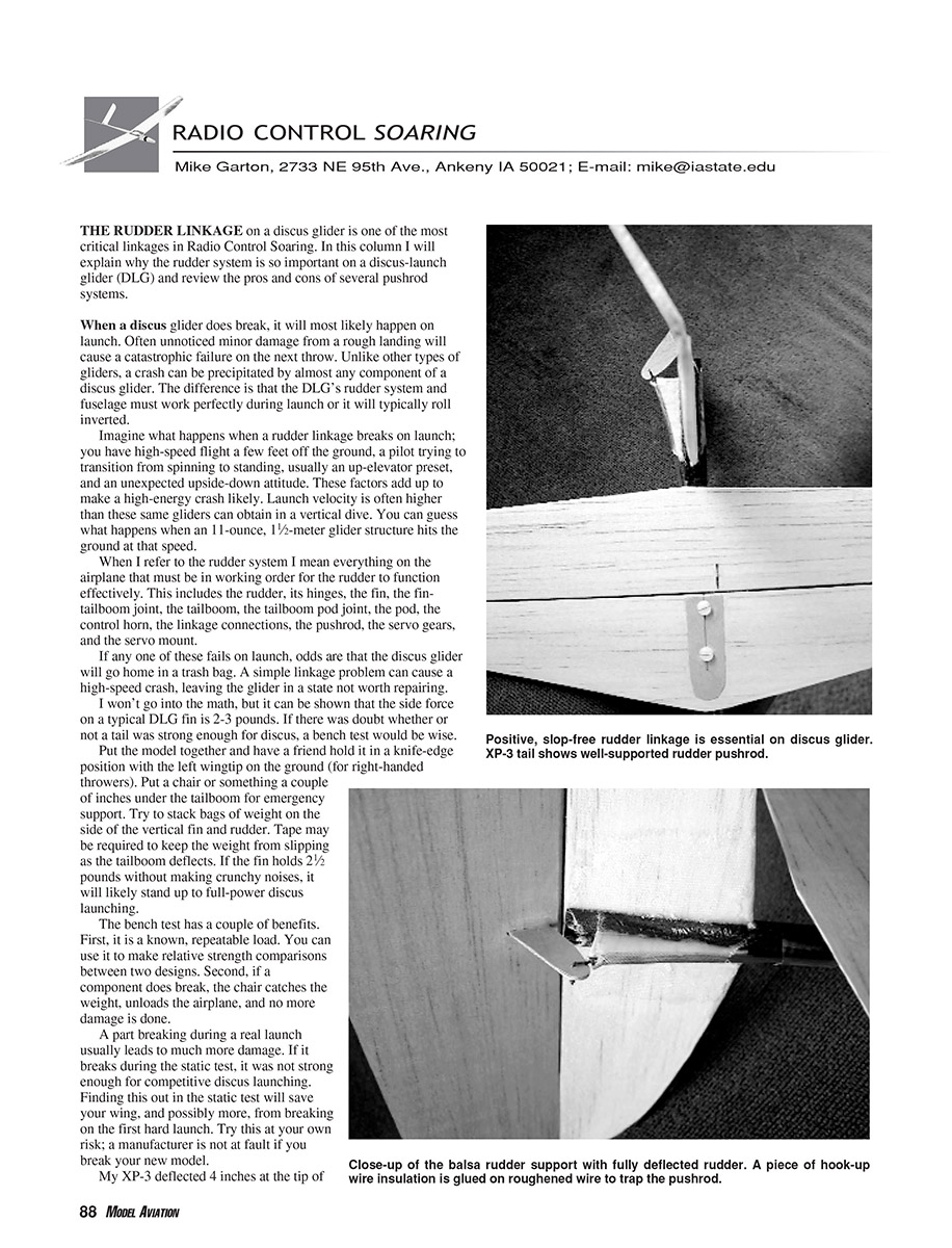
When I refer to the rudder system I mean everything on the airplane that must be in working order for the rudder to function effectively:
- rudder and its hinges
- fin and fin–tailboom joint
- tailboom and tailboom–pod joint
- pod
- control horn
- linkage connections and pushrod
- servo gears and servo mount
If any one of these fails on launch, odds are the discus glider will go home in a trash bag. A simple linkage problem can cause a high-speed crash that leaves the glider beyond reasonable repair.
Bench test for tail strength
If there is doubt about whether a tail is strong enough for discus, perform a bench test:
- Put the model together and have a friend hold it in a knife-edge position with the left wingtip on the ground (for right-handed throwers).
- Put a chair or something a couple of inches under the tailboom for emergency support.
- Stack bags of weight on the side of the vertical fin and rudder. Tape may be required to keep the weight from slipping as the tailboom deflects.
If the fin holds a 2-1/2-pound load without making crunchy noises, it will likely stand up to full-power discus launching.
Benefits of the bench test:
- It is a known, repeatable load you can use to compare designs.
- If a component breaks during the test the chair catches the weight, unloading the airplane and preventing further damage.
A part that breaks during a real launch usually leads to much more damage. If it breaks during the static test, it was not strong enough for competitive discus launching. Finding this out in the static test will save your wing, and possibly more, from breaking on the first hard launch. Try this at your own risk; a manufacturer is not at fault if you break your new model.
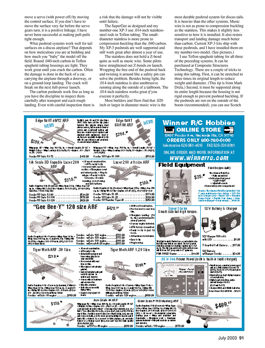
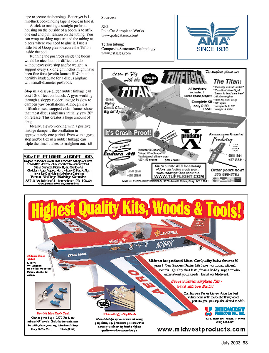
My XP-3 deflected 4 inches at the tip of the rudder with a 2-1/2-pound load and was completely silent during the test. Weaker airplanes will deflect excessively or break under the same load. You would be surprised how much some fuselage pods flex under the wing (and eventually break) on non–carbon-reinforced pod designs. The calculated 2- to 3-pound loads on the fin also explain why most discus models use fiberglassed balsa surfaces rather than thin balsa alone.
Real-world examples
Last summer I forgot to reinstall a retainer on my XP-3's rudder pushrod. My preflight inspection should have caught it. The pushrod pulled loose on a hard launch; the model rolled inverted. I let go of the up-elevator preset, and the airplane completed the 90 mph roll 4 feet off the deck. The correction and problem happened in less than a second — a combination of luck and reflexes saved the airplane. I counted my blessings and quit for the day.
At the 2002 Mid South contest, Bruce Davidson had the rudder pull-pull string break on launch on his polyhedral XP-3. Using elevator control alone, Bruce completed the four-minute max and landed in bounds on a large sod farm. He said that was the last time he ever used pull-pulls on a discus glider.
Pushrod systems — options, pros and cons
What pushrod systems work well for tail surfaces on a discus airplane depends on how meticulous you are at building and how carefully you handle the model off the field.
Pull-pull strings
- Pros: Potentially the lightest system.
- Cons: Lines need periodic retensioning; there is constant compression force on the hinges; even Kevlar or Spectra strings cannot be made as solid as a pushrod. In practice I have never been successful at making pull-pulls tight enough. They can be unreliable on hard launches.
Round carbon (.040-inch) in Teflon spaghetti tubing
- Pros: Light and low profile.
- Cons: Works great until you crack the carbon. Damage is often done during transport, through doorways, or on ground-loop landings; a crack can lead to failure on the next full-power launch. Requires diligent inspection after transport and rough landings; some damage may be invisible until failure.
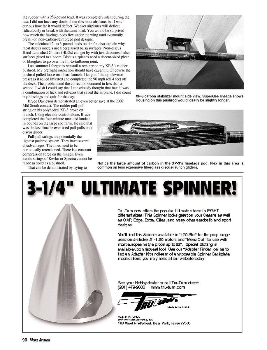
.014-inch stainless-steel rod in Teflon tubing
- Pros: Very light and unobtrusive, runs nicely along the outside of a tailboom. My XP-3 and the SuperGee use these and they worked well when well supported.
- Cons: More prone to compression buckling than .040 carbon; does not hold a Z-bend as well as music wire. Some pilots have straightened out Z-bends on launch — wrapping the free end back and twisting it around like a safety pin can help. Works great if executed perfectly.
Music wire (.020 inch or larger)
- Pros: Most durable for discus tails, less prone to compression buckling, less sensitive to installation details, and resists transport and landing damage better than carbon or thin stainless.
- Cons: Heavier than the other systems. Many builders and fliers prefer this for durability; current XP-3 kits ship with these pushrods.
Teflon tubing — tips for use
I use Teflon spaghetti tubing for all three of the preceding systems. A few tricks:
- The tubing can be stretched to three times its original length to reduce weight and diameter (tip from Mark Drela).
- The tubing must be supported along its entire length because the housing is not rigid enough to prevent pushrod buckling.
- If pushrods are run on the outside of the boom (recommended), you can use Scotch tape to secure the housings. Better yet, use 1-mil-thick bookbinding tape if you can find it.
- To make a straight housing on the outside of a boom, affix one end and pull tension on the tubing. Wrap masking tape around the tubing where you need to glue it. I use a little Goop glue to secure the Teflon inside the pod.
Running pushrods inside the boom is possible but difficult without introducing excessive slop and/or weight. A support every six or eight inches might suffice for a javelin-launch HLG, but it is inadequate for a discus airplane with small-diameter pushrods.
Effects of slop and gyros
Slop in a discus-glider rudder linkage can cost tens of feet on launch. A gyro working through a sloppy rudder linkage is slow to damp yaw oscillations. Stopped video frames show that most discus airplanes initially yaw about 20° on release, creating a huge amount of drag.
Ideally, a gyro working with a positive linkage dampens the oscillation in approximately one period. Even with a gyro, slop and/or flex in a rudder linkage can triple the time it takes to straighten out.
Sources
- XP-3: Pole Cat Aeroplane Works — www.polecataero.com/
- Teflon tubing: Composite Structures Technology — www.cstsales.com/
Transcribed from original scans by AI. Minor OCR errors may remain.

