
Radio Control Soaring
Darwin Barrie
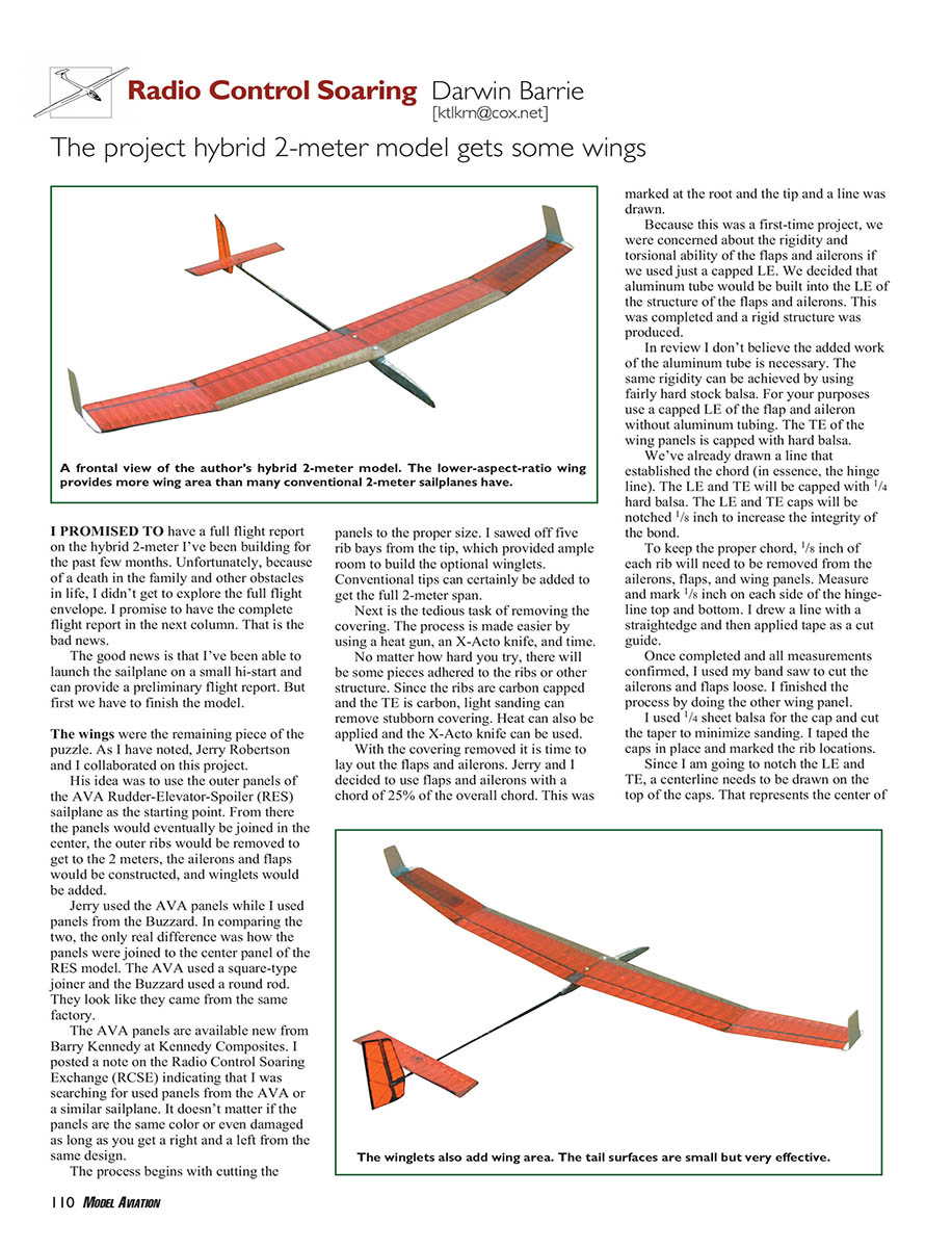
The project hybrid 2-meter model gets some wings
I promised to have a full flight report on the hybrid 2-meter I’ve been building for the past few months. Unfortunately, because of a death in the family and other obstacles in life, I didn’t get to explore the full flight envelope. I promise to have the complete flight report in the next column. That is the bad news.
The good news is that I’ve been able to launch the sailplane on a small hi-start and can provide a preliminary flight report. But first we have to finish the model.
Wings: starting point and panels
The wings were the remaining piece of the puzzle. As I have noted, Jerry Robertson and I collaborated on this project. His idea was to use the outer panels of the AVA Rudder-Elevator-Spoiler (RES) sailplane as the starting point. From there the panels would eventually be joined in the center, the outer ribs would be removed to get to the 2-meter span, the ailerons and flaps would be constructed, and winglets would be added.
Jerry used the AVA panels while I used panels from the Buzzard. In comparing the two, the only real difference was how the panels were joined to the center panel of the RES model. The AVA used a square-type joiner and the Buzzard used a round rod. They look like they came from the same factory.
The AVA panels are available new from Barry Kennedy at Kennedy Composites. I posted a note on the Radio Control Soaring Exchange (RCSE) indicating that I was searching for used panels from the AVA or a similar sailplane. It doesn’t matter if the panels are the same color or even damaged as long as you get a right and a left from the same design.
The process begins with cutting the panels to the proper size. I sawed off five rib bays from the tip, which provided ample room to build the optional winglets. Conventional tips can certainly be added to get the full 2-meter span.
Removing the covering
Next is the tedious task of removing the covering. The process is made easier by using:
- a heat gun
- an X-Acto knife
- time and patience
No matter how hard you try, there will be some pieces adhered to the ribs or other structure. Since the ribs are carbon-capped and the trailing edge is carbon, light sanding can remove stubborn covering. Heat can also be applied and the X-Acto knife used to free the material.
Laying out flaps and ailerons
With the covering removed it is time to lay out the flaps and ailerons. Jerry and I decided to use flaps and ailerons with a chord of 25% of the overall chord. This was marked at the root and the tip and a line was drawn.
Because this was a first-time project, we were concerned about the rigidity and torsional stiffness of the flaps and ailerons if we used just a capped leading edge (LE). We decided that aluminum tube would be built into the LE structure of the flaps and ailerons. This produced a rigid structure.
In review I don’t believe the added work of the aluminum tube is necessary. The same rigidity can be achieved by using fairly hard stock balsa. For most builders, use a capped LE of the flap and aileron without aluminum tubing. The trailing edge (TE) of the wing panels is capped with hard balsa.
We had already drawn a line that established the chord (in essence, the hinge line). The LE and TE will be capped with 1/4" hard balsa. The LE and TE caps were notched 1/8" to increase the integrity of the bond.
To keep the proper chord, 1/8" of each rib needed to be removed from the ailerons, flaps, and wing panels. Measure and mark 1/8" on each side of the hinge line top and bottom. I drew a line with a straightedge and then applied tape as a cut guide. Once completed and all measurements confirmed, I used my bandsaw to cut the ailerons and flaps loose, then finished the process on the other wing panel.
I used 1/4" sheet balsa for the caps and cut the taper to minimize sanding. I taped the caps in place and marked the rib locations.
Notching and fitting caps
Since I was going to notch the LE and TE, a centerline needed to be drawn on the top of the caps. That represents the center of the notch. I used my bandsaw to cut the notches and fine-tuned each notch with a flat, thin file. A Dremel can be used, with a file used for cleanup.
I test-fit each piece and used a straightedge to true the cap. When satisfied I glued the caps in place and sanded them to match the ribs. I installed corner gussets at each corner of the cap, tip, and root.
Hinging and servo installation
The flaps are hinged on the bottom and the ailerons on the top. I sanded a slight bevel into the flap cap to allow approximately 1/8" of up-flap travel. A bevel was sanded into the bottom of each aileron. Determine how much to sand based on the max downward deflection you expect.
After the servo locations were established I Dremeled holes into the ribs for the servo wires (near the spar).
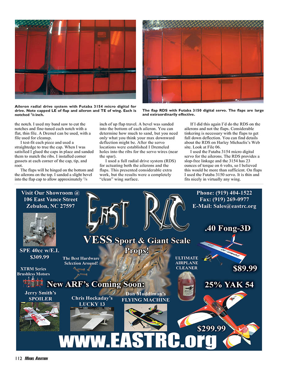
I used a full radial drive system (RDS) for actuating both the ailerons and the flaps. This presented considerable extra work, but the results were a completely clean wing surface.
If I did this again I'd do the RDS on the ailerons and not the flaps. Considerable tinkering is necessary with the flaps to get full down deflection. You can find details about the RDS on Harley Michaelis's web site — look at File 06.
I used the Futaba 3154 micro digital servo for the ailerons. The RDS provides a slop-free linkage and the 3154 has 23 ounces of torque on 6 volts, so I believed this would be more than sufficient. On flaps I used the Futaba 3150 servo. It is thin and fits nicely in virtually any wing.
Joining the wing panels
Before joining the wing panels I determined the bolt-hole locations and Dremeled a "half round" into each panel. This was necessary because the root ribs were carbon-capped and would have been difficult to drill without a guide hole. Once joined, I drilled the true 1/4" hole, applied cyanoacrylate glue, and drilled the hole again.
The wing rod at the center was a stock aluminum 1/2" joiner rod I obtained from Don Richmond at Hilaunch.com. Since the wing panels are the outer panels of a larger model, there are only a few inches on each side of center to insert the rod. I cut the rod to the proper length and fit it to the wings. The dihedral was perfect.
I also built a 1/4" carbon-rod alignment pin forward of the TE. Once all the servo detail was completed, the wings were joined.
I used epoxy and micro filler for the joint and thoroughly coated the main wing rod. First I scuffed it with 80-grit sandpaper and cleaned it. The center was covered with 2-ounce fiberglass cloth that was 2 inches wide. The cloth aft of the spar was trimmed to the ribs after curing.
The main structure was complete. I attached the wing to the fuselage with 1/4-20 nylon bolts. The rudder and elevator were made operational and the CG was checked. I used an initial CG of 35% of the chord as a safe starting point.
Tow hook location and initial test flights
I wasn't sure what to do about tow hook location on a new model with no flight history. Jerry said he uses a removable tow hook until he has established the CG. This involves making a molded fixture that is taped to the fuselage.
Jerry’s method:
- Tape waxed paper to the bottom of the fuselage in the range where the CG will be located.
- Epoxy two layers of 4- to 6-ounce cloth in place.
- After curing, epoxy a tow hook in place and secure it with a buildup of epoxy and micro filler, forming the fill with a finger and alcohol before it cures.
- When cured, add a couple more layers of cloth over the entire structure, then trim and sand to final form.
Initial test tosses showed the CG to be too far forward. I removed nose weight until the hand tosses felt comfortable.
I taped on the tow-hook fixture with fiberglass-stranded tape approximately 1/8" in front of the CG. My short hi-start is perfect for 150-foot launches, which is ideal for initial flights.
I launched the sailplane and the trajectory was nearly ideal. The CG was still a bit forward and I removed more weight. I moved the tow hook back slightly.
The next launch was perfect. I felt a bump on the way up, and the model immediately caught a thermal for a 10-minute ride. During the flight I was able to determine what settings I needed to modify.
After a couple more launches the flap/elevator landing compensation was set. What a great-flying airplane!
Next month I'll wrap it up with a full flying report and some contest reports.
MA
Sources
- Harley Michaelis — http://genie.homepage.com
- Hilaunch.com — (858) 539-6029 — www.hilaunch.com
- Kennedy Composites — (972) 602-3144 — www.kennedycomposites.com
- Radio Control Soaring Exchange — www.eclipse.net/~mikel/rcse/rcse.htm
Transcribed from original scans by AI. Minor OCR errors may remain.

