
How to build a composite fuselage
Radio Control Soaring — Darwin Barrie ([email protected])
I received positive feedback on my column about the preparation for fiberglass. Many who are new to composite building were unaware of the preparation needed to finish a fiberglass fuselage.
This month I will take that topic a bit further and discuss the process to build your own composite fuselage. This will be a two-part article discussing the new hybrid Two-Meter design Jerry Robertson and I are building.
Design intent and overall plan
Noted designer, builder, and pilot Jerry Robertson and I discussed building a new world-beater Two-Meter design. We agreed the fuselage would be a pod-and-boom style, which provides a light, strong fuselage that is easy to build. A nose cone would be incorporated.
The plan was to use the carbon-fiber sock method for simplicity, strength, and weight. This process is great for the homebuilder to make a one-off fuselage and requires no male/female molds or specialized tools.
The first task was to acquire a tailboom. Jerry felt that the longer the tail moment, the smaller the tail surfaces could be; this would ease construction and keep weight down. I acquired an Allegro Two-Meter tailboom — 33.5 inches — which was perfect.
We laid out the nose moment of the fuselage based on several factors. One goal was to make the fuselage cross-section as small as possible. We also wanted the nose moment long enough to comfortably fit all the radio gear and avoid having to add useless nose weight.
Jerry chose the basic planform of his successful Sisu design (kitted by Northeast Sailplane Products, www.nesail.com). It has a unique nose that sweeps downward. One of Jerry’s concerns was servo location and achieving as straight a line as possible for the pushrods down the tailboom; the Sisu style makes this task a bit simpler.
I laid out a more conventional fuselage without the down sweep. The pushrods lined up nicely and the fuselage was easier to construct. The nose moment from the leading edge to the nose is 10.75 inches.
The first thought was a pedestal-type wing mounting, but that became unfeasible with this type of construction.
Foam shaping and basic pod construction
Blue or pink foam is necessary to make the fuselage. Either is easy to cut, carve, and sand. I used pink foam because it was what I had available.
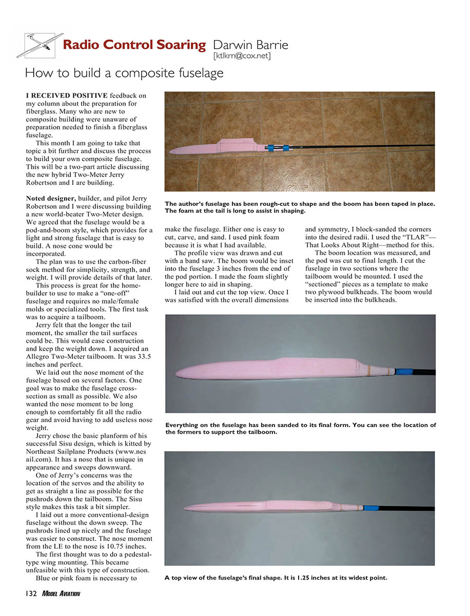
I drew and cut the profile view with a band saw. The boom would be inset into the fuselage 3 inches from the end of the pod portion. I left the foam slightly longer here to aid shaping.
I laid out and cut the top view. Once satisfied with overall dimensions and symmetry, I block-sanded the corners into the desired radii using the “TLAR” — That Looks About Right — method.
The boom location was measured and the pod was cut to final length. I cut the fuselage in two sections where the tailboom would be mounted and used the sectioned pieces as templates to make two plywood bulkheads. The boom would be inserted into the bulkheads.
I drilled the bulkheads and carefully fit them to the boom at the proper location, taking into account the taper of the boom. I drilled the pieces of foam to accept this assembly. I prepped the boom for epoxy by roughing the outer surface with sandpaper and cleaning it with alcohol. The entire assembly was glued to the pod with five-minute epoxy, taking care to ensure everything was in proper alignment.
Molding in pushrod housings
One thing I have learned is that I can mold in the pushrod housings before using the carbon sock. This greatly eases construction later and provides secure pushrods in the fuselage. In this case I used .050 carbon pushrods.
The process:
- Place the servos on the profile view to determine servo-arm location and height.
- Scribe a straight line on the foam for the full-length location of the pushrod. Because the fuselage pod tapers into the boom, avoid significant bends that would cause binding.
- With the stabilizer already built, determine the elevator exit location on the top of the boom. The rudder pushrod will exit the end of the boom.
I used a Dremel tool with a router attachment to rout a channel for the pushrod housing. Approximately 4 inches in front of the boom opening, the channel was tapered inward to provide a smooth transition into the boom. A smooth transition was achieved by trial and error to create no binding.
An inch of the front of each housing was taped off so it would not adhere to the fuselage sides during the layup and to keep epoxy from getting into the tubes. Pushrods were inserted to prevent crushing or kinking of the housings. After getting everything lined up, the housings were epoxied into the foam channels. Toward the tail where the taper occurs, I mixed microballoons and epoxy to fill the void between the fuselage sides where the foam was cut deeper.
Reinforcement and layup
The fuselage was then prepared for layup. I reinforced several areas with carbon-tow material and fiberglass cloth. A strip of tow was epoxied on each side and on the top and bottom. I laid 1-inch fiberglass cloth along the bottom the full length and doubled it in the areas of the tow hook, wing saddle, and forward fuselage.
After curing, I sanded the surface smooth without cutting into the fiberglass weave. All layup was done in one process using West System epoxy, thinned slightly with alcohol.
Items necessary for the fuselage layup:
- Carbon sock, part C9361 (2-inch), available from CST — The Composites Store (www.cstsales.com).
- West System epoxy and microballoon filler.
- 16-gauge (or similar) wire and a 1-gallon can, jug, or bottle with a handle (for mixing and dipping).
- A place to hang the assembly while the layup cures (I used a doorway with the door open overnight to the outside to give a clear working area).
- Standard hand tools (Dremel with router attachment, sandpaper, measuring tools, drill press, etc.).
The carbon sock initially looks heavy; when completed and sanded it becomes extremely thin but very strong. The sock material is also available in fiberglass.
I’ll complete the fuselage and discuss the wings in next month’s article. I’ll wrap up this month with the construction of the tail feathers.
Tail feathers — stabilizer and rudder
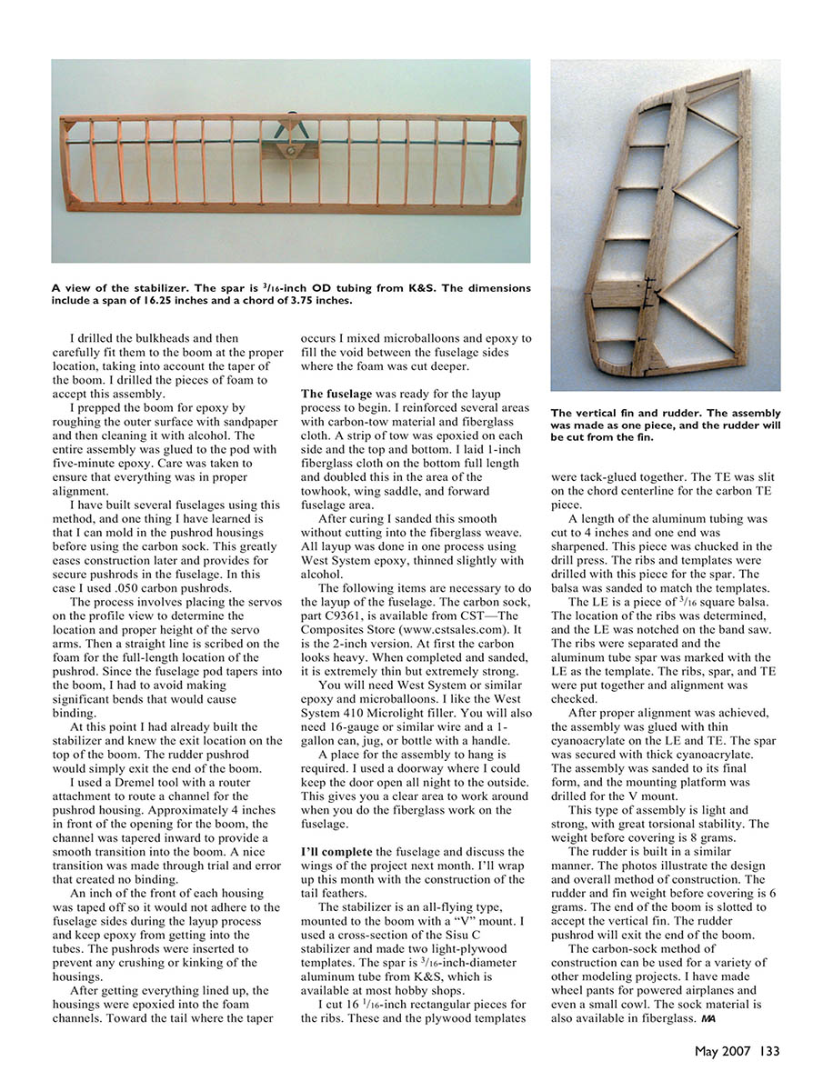
The stabilizer is an all-flying type, mounted to the boom with a “V” mount. I used a cross-section of the Sisu C stabilizer and made two light-plywood templates. The spar is a 3/16-inch-diameter aluminum tube from K&S, which is available at most hobby shops.
I cut 16 1/16-inch rectangular pieces for the ribs. These and the plywood templates were tack-glued together. The trailing edge (TE) was slit on the chord centerline for the carbon TE piece.
A length of the aluminum tubing was cut to 4 inches and one end was sharpened. This piece was chucked in the drill press and used to drill the ribs and templates for the spar. The balsa was sanded to match the templates. The leading edge (LE) is a piece of 3/16-inch square balsa. The location of the ribs was determined and the LE was notched on the band saw. The ribs were separated and the aluminum tube spar was marked using the LE as the template. The ribs, spar, and TE were assembled and alignment was checked.
After proper alignment was achieved, the assembly was glued with cyanoacrylate onto the LE and TE. The spar was secured with thin CA. The assembly was sanded to its final form and the mounting platform was drilled for the V mount. This assembly is light and strong with good torsional stability. Weight before covering is 8 grams.
The rudder is built in a similar manner. The photos (in the original article) illustrate the design and overall method of construction. The rudder and fin weigh 6 grams before covering. The end of the boom is slotted to accept the vertical fin. The rudder pushrod will exit the end of the boom.
Final notes
The carbon-sock method of construction can be used for a variety of modeling projects. I have made wheel pants for powered airplanes and even a small cowl. The sock material is also available in fiberglass.
Transcribed from original scans by AI. Minor OCR errors may remain.

