
Radio Control System Installation 2003/05
Last month in this series I gave you a basic introduction—from an informational and identification standpoint—that would enable you to purchase your first Radio Control (RC) system. This month I will take you from the shipping box to the model aircraft. The discussion will cover the installation aspects of a typical RC system.
Dual Conversion and Narrow Band
There are two terms I didn’t discuss last month which have been brought to my attention by several reader letters.
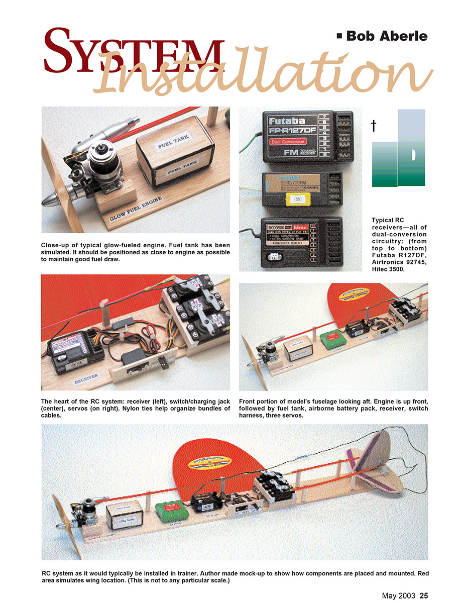
With regard to RC receivers, “dual conversion” is a technique in which the receiver operates with two stages of frequency conversion rather than one. The basic dual-conversion receiver employs two crystals rather than one. Because of the extra level of conversion, these receivers can be made more selective and more immune to certain interference situations. The basic dual-conversion receiver will, by nature, be slightly larger in size, weigh a little more, and be slightly more expensive than a single-conversion receiver. There is nothing wrong with single conversion; several lines of RC receivers have used that type of circuitry successfully for many years. However, most receiver labels these days will identify the product as “dual conversion.”
Along these same lines you will see the expression “narrowband” performance. When we obtained our 50 RC channels in 1982, we were committed to operating in a much tighter channel environment. Older RC channel separation was 80 kilohertz (kHz), and the new channels were placed at a narrow spacing of 20 kHz. Meeting that demand required considerable improvements in RC electronic circuitry. Anything you can purchase today will almost exclusively be “narrow band,” meaning it will operate safely with an adjacent channel operating next to you on the flightline.
Batteries and Charging
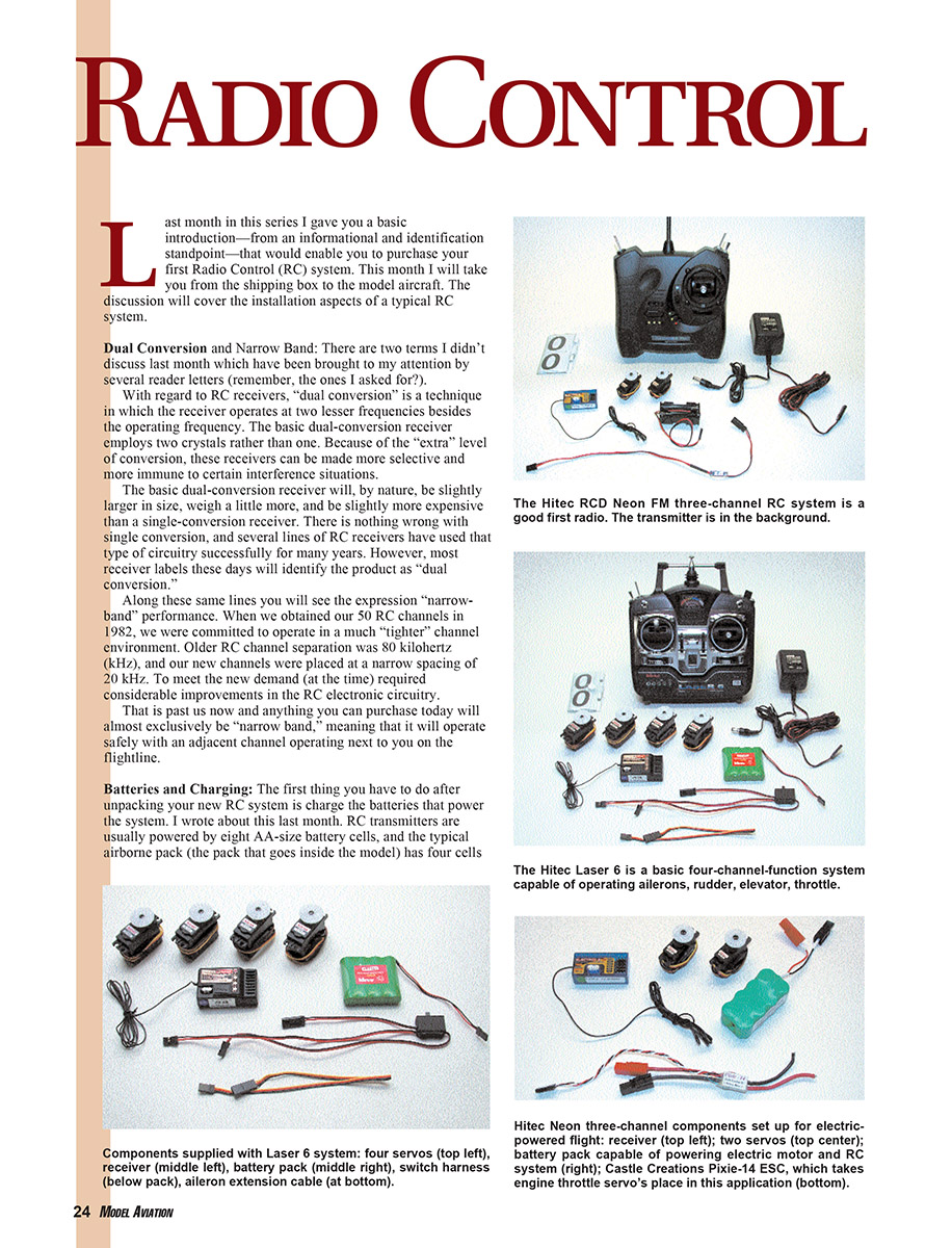
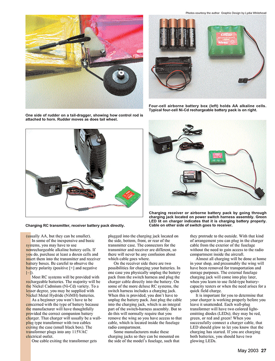
The first thing you have to do after unpacking your new RC system is charge the batteries that power the system. RC transmitters are usually powered by eight AA-size battery cells, and the typical airborne pack (the pack that goes inside the model) has four cells (usually AA, but they can be smaller).
In some inexpensive and basic systems, you may have to use nonrechargeable alkaline battery cells. If you do, purchase at least a dozen cells and insert them into the transmitter and receiver battery boxes. Be careful to observe the battery polarity (positive [+] and negative [–]).
Most RC systems will be provided with rechargeable batteries. The majority will be the Nickel Cadmium (Ni-Cd) variety. To a lesser degree, you may be supplied with Nickel Metal Hydride (NiMH) batteries.
As a beginner you won't have to be concerned with the chemistry because the manufacturer will have provided the correct companion battery charger. That charger will usually be a wall-plug type transformer with two cables exiting the small black box. The transformer plugs into any 115VAC electrical outlet.
One cable exiting the transformer gets plugged into the charging jack located on the side, bottom, front, or rear of the transmitter case. The connectors for the transmitter and receiver are different, so there will never be any confusion about which cable goes where.
On the receiver side there are two possibilities for charging your batteries. In one case you physically unplug the battery pack from the switch harness and plug the charger cable directly into the battery. On some of the more deluxe RC systems, the switch harness includes a charging jack. When this is provided, you don't have to unplug the battery pack—just plug the cable into the charging jack, which is an integral part of the switch-harness assembly. To reach this jack you will normally have to remove the wing so you have access to the cable inside the fuselage radio compartment.
Some manufacturers make these charging jacks so they can be mounted on the side of the model's fuselage and protrude to the outside. With that arrangement you can plug in the charger cable from the exterior of the fuselage without gaining access to the radio compartment.
Almost all charging will be done at home in your shop, and presumably the wing will have been removed for transportation and storage purposes. The external fuselage charging jack will come into play later, when you learn to use field-type battery-capacity testers or when a quick field charge is needed.
It is important to determine that your charger is working properly before leaving it unattended. Each wall-plug transformer will have LEDs (they may be red, green, or red and green). When you successfully connect a charger cable, the LED should glow to indicate charging has started. If you are charging both batteries, you should have two glowing LEDs.
The first time you charge your new battery packs, you are advised to leave them on charge for a full 24 hours. After that, it is normal to leave the charger on overnight. These batteries have been designed to take hundreds of recharging cycles. Most batteries will provide several years of regular service without degrading in performance.
Because your RC-system charger operates at a low level, nothing catastrophic will happen if you forget and leave a charger on for 48 hours. However, don’t play the “I’ll put back in what I took out” game; that is, you use the RC system for two hours and recharge it for only two hours. The battery chemistry requires a charge period of at least 10 hours each time. If you plan on flying the next day, put the charger on the night before. If you don't fly the next day because of bad weather and a week goes by, charge it again. When in doubt, charge again; it can't hurt, but it sure can help.
One final caution: when charging, make sure you plug your charger into a 115VAC outlet that remains on all the time. If you choose an outlet that is operated by a wall switch and later turn that switch off, your charger will be off and your batteries will not be charged. The next day you could have a failure in flight because the batteries were never charged.
The subject of batteries is extremely important to the RC system's operation. As I progress in this series I will provide more information about battery-capacity testing at home and at the flying field.
Connectors and Wiring Polarity
Your RC transmitter is a self-contained unit that you hold in your hands. On the aircraft side you have a series of components that must be installed or mounted inside the aircraft fuselage; then all of those components must be connected so you have an operating airborne RC system.
That interconnecting is done with connectors. They allow you to make and break electrical connections without needing to solder wire; the manufacturer has already done the soldering and/or mechanical wire crimping for you.
Years ago, types of connectors varied considerably from manufacturer to manufacturer. One brand would not work with another; wire color coding and polarity order also varied. Things have become more standardized throughout the industry, but the best advice I can give you when starting out is: never mix or match different brands of connectors.
- If you purchased a Futaba RC system, use only Futaba components and Futaba connectors.
- Use only the charger that was supplied with your system.
For now, while you are getting started, use the components as supplied. You may make exceptions to this rule as you gain experience.
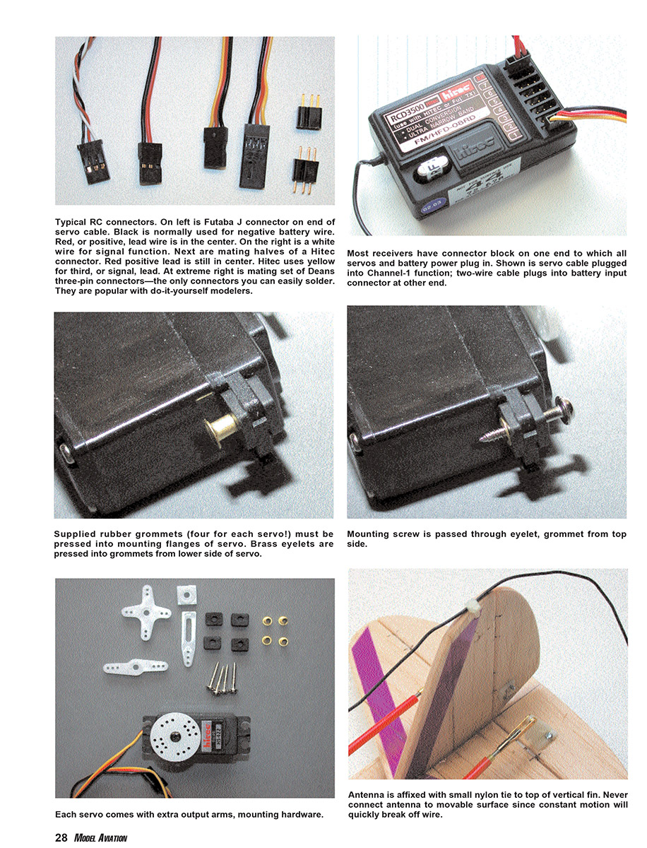
Most connectors have keyways or slots that permit them to be connected only one way. Wiring convention used by most of the RC industry today has the positive (+) pin or wire in the center of a basic three-pin connector.
Battery power circuits use two wires, and servo cables have three wires. With the positive wire in the center, if you are actually able to plug a connector in backward, the circuit will be incomplete. Nothing would work, but at least nothing would be short-circuited and blown out.
Basic RC Component Installation
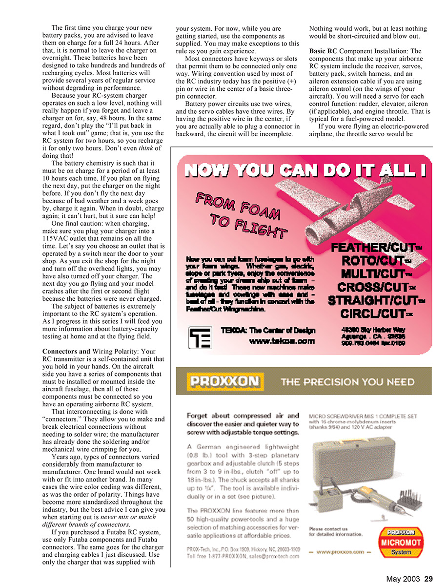
The components that make up your airborne RC system include the receiver, servos, battery pack, switch harness, and the aileron extension cable if you are using aileron control (on the wings of your aircraft). You will need a servo for each control function: rudder, elevator, aileron (if applicable), and engine throttle. That is typical for a fuel-powered model.
If you are flying an electric-powered airplane, the throttle servo is replaced by an electronic speed control (ESC). You plug the ESC cable into the same throttle port (connector) on your receiver as you would a throttle servo. Operating the throttle control stick on your transmitter then varies the motor's speed.
Most ESCs intended for smaller electric-powered models contain an internal Battery Eliminator Circuit (BEC). It allows you to use one battery pack to power both the motor and your RC system on a shared basis. I'll write more about this when I get into electric-powered models.
Placement of the RC components involves a couple of considerations. Most important, these radio parts add weight to your model. The components' location can affect your aircraft's center of gravity (CG) or balance point. An improperly balanced model (too tail-heavy or nose-heavy) is not going to fly well, or at all. Another consideration is the length of the cables supplied with the various components. Failure to arrange them logically can leave you with cables that are too short or too long.
Traditionally, the RC battery pack is placed up front, just behind the engine and fuel tank. Most basic aircraft designs have shorter nose lengths and longer tail lengths, hence the need for more weight forward. Your battery pack will probably be the heaviest weight in the system, so place it to best advantage while attempting to achieve the correct balance.
Working back from the model's nose, the item behind the battery pack should be the throttle servo, which must be mechanically connected to the engine carburetor. If you have an electric-powered aircraft, the ESC should be located in roughly the same area as the throttle servo. After this we should be approximately at the position of the wing's leading edge.
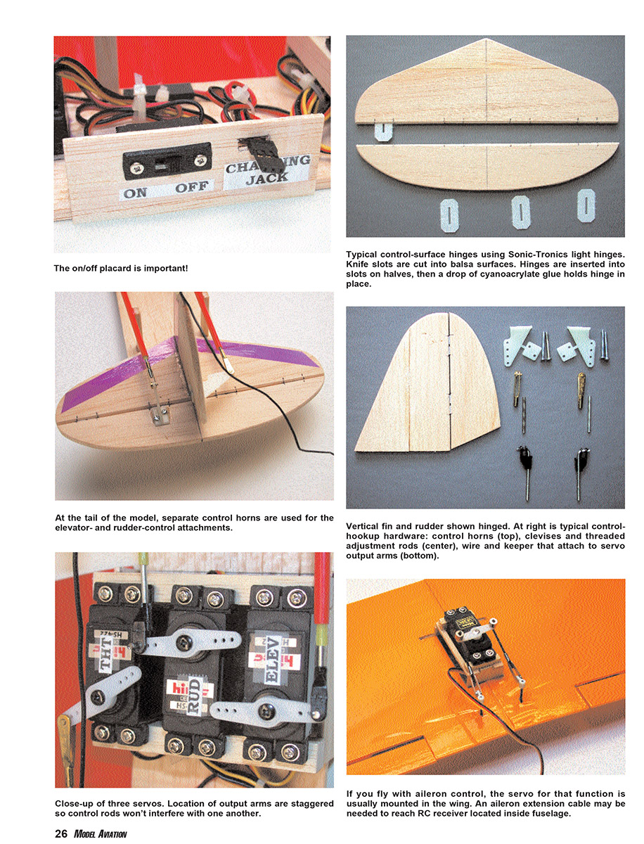
The wing usually covers the model's radio compartment. When you remove the wing (top- or bottom-mounted), you can access this section. The front portion of this compartment is where the RC receiver is generally installed. Behind the receiver (in roughly the middle of the space) is a good place for the power (on/off) switch and the charging jack. The rudder and elevator servos go toward the aft portion of the compartment.
Some modelers locate the throttle servo back in this aft position. If they do, they must run a control rod forward to the engine throttle. With this arrangement, all the servo cables (and the ESC cable for electric power) can easily reach the mating connector on the receiver.
If you are using aileron control, plug an aileron extension cable into the receiver first. The other end of this extension can pass up toward the wing-mounted aileron servo. When you attach the wing before flying, that aileron servo must be connected to the extension cable. Likewise, you must disconnect the aileron servo cable from the extension cable when you remove the wing for transportation or storage.
The remaining installation involves running control rods back to the tail surfaces of the aircraft. The output of the rudder servo up front must be connected to the movable rudder at the model's tail, and the elevator servo output must be connected to the elevator control surface in the rear. More details of these control-rod hookups will be discussed in the installment dealing with model assembly.
Most aircraft have a tail-dragger configuration, in which the model's tail rests on the ground. A tail wheel is attached to the rudder and moves with the rudder to steer the aircraft when taxiing. Aircraft that do not have ground-maneuvering capability are usually hand launched.
The other popular configuration is tricycle landing gear (trike gear). In this arrangement the aircraft sits relatively level on two rear-mounted main wheels and a single nose wheel. That nose wheel is mechanically connected to the rudder servo so the aircraft can be steered on the ground. Trike gear is probably the easier configuration for the rank beginner to handle and learn, but hooking up the nose-wheel steering can be more complex.
The last important item is deploying the receiver antenna wire properly. Each modern RC receiver has a wire antenna measuring approximately 40 inches that exits its case. The smaller the aircraft, the harder it is to deploy this antenna wire properly.
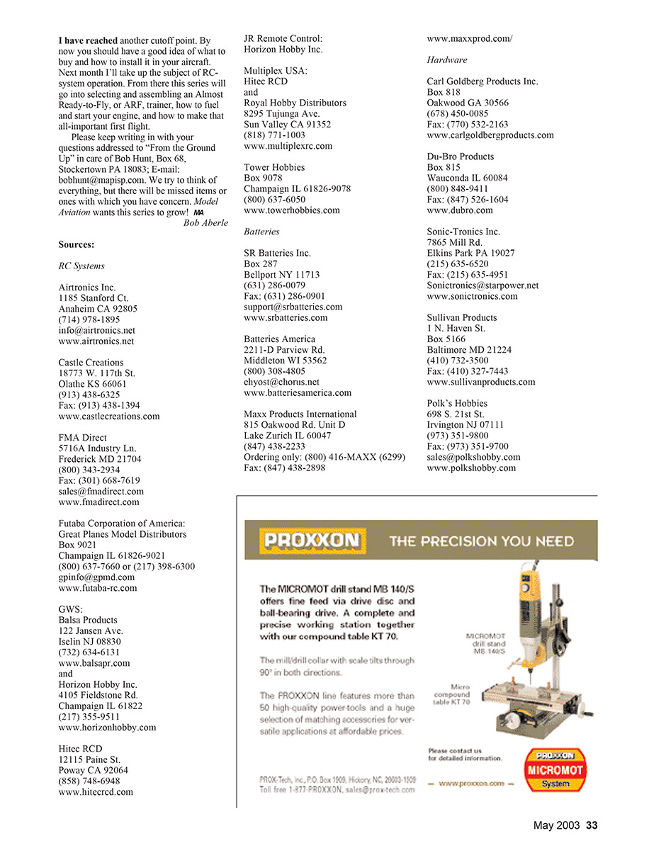
The time-honored method is to run the antenna wire from the receiver directly to the outside of the fuselage through a small-diameter hole, then out to the rear of the aircraft where it can be attached to the top of the vertical fin or to the tip of the stabilizer.
The antenna should never be attached to a movable tail surface such as the rudder or elevator; the constant flexing could eventually break the wire. Under no circumstances should you reduce the antenna wire's length. Doing so might detune the output stage of your receiver and greatly reduce radio range. Several excellent reduced-size antennas are available for use with smaller models; I will get to that later. For now the beginner should concentrate on using the full-length antenna.
These wire receiver antennas can pick up more than received radio signals; they can also pick up electrical noise generated by servo motors. Keeping this in mind, route your antenna away from the servo actuators when running it to the rear of the aircraft. Try to get the antenna outside and away from these noise generators.
RC System Mock-Up
To put everything in the proper physical size and location, I have included a mock-up of a typical airborne RC system. It is laid out exactly as the RC equipment would be installed in your aircraft. Keep it as a reference for RC-model installations.
By now you should have a good idea of what to buy and how to install it in your aircraft. Next month I'll take up the subject of RC-system operation. From there this series will go into selecting and assembling an Almost Ready-to-Fly (ARF) trainer, how to fuel and start your engine, and how to make that all-important first flight.
Please keep writing in with your questions addressed to "From the Ground Up" in care of Bob Hunt, Box 68, Stockertown PA 18083; E-mail: [email protected]. We try to think of everything, but there will be missed items or ones with which you have concern. Model Aviation wants this series to grow!
Bob Aberle
Sources
RC Systems
- Airtronics Inc., 1185 Stanford Ct., Anaheim CA 92805; (714) 978-1895; [email protected]; www.airtronics.net
- Castle Creations, 18773 W. 117th St., Olathe KS 66061; (913) 438-6325; Fax: (913) 438-1394; www.castlecreations.com
- FMA Direct, 5716A Industry Ln., Frederick MD 21704; (800) 343-2934; Fax: (301) 668-7619; [email protected]; www.fmadirect.com
- Futaba Corporation of America / Great Planes Model Distributors, Box 9021, Champaign IL 61826-9021; (800) 637-7660 or (217) 398-6300; [email protected]; www.futaba-rc.com
- GWS / Balsa Products, 122 Jansen Ave., Iselin NJ 08830; (732) 634-6131; www.balsapr.com
- Horizon Hobby Inc., 4105 Fieldstone Rd., Champaign IL 61822; (217) 355-9511; www.horizonhobby.com
- Hitec RCD, 12115 Paine St., Poway CA 92064; (858) 748-6948; www.hitecrcd.com
- JR Remote Control — Horizon Hobby Inc.
- Multiplex USA — Hitec RCD and Royal Hobby Distributors, 8295 Tujunga Ave., Sun Valley CA 91352; (818) 771-1003; www.multiplexrc.com
- Tower Hobbies, Box 9078, Champaign IL 61826-9078; (800) 637-6050; www.towerhobbies.com
Batteries
- SR Batteries Inc., Box 287, Bellport NY 11713; (631) 286-0079; Fax: (631) 286-0901; [email protected]; www.srbatteries.com
- Batteries America, 2211-D Parview Rd., Middleton WI 53562; (800) 308-4805; [email protected]; www.batteriesamerica.com
- Maxx Products International, 815 Oakwood Rd. Unit D, Lake Zurich IL 60047; (847) 438-2233; Ordering: (800) 416-MAXX (6299); Fax: (847) 438-2898; www.maxxprod.com
Hardware
- Carl Goldberg Products Inc., Box 818, Oakwood GA 30566; (678) 450-0085; Fax: (770) 532-2163; www.carlgoldbergproducts.com
- Du-Bro Products, Box 815, Wauconda IL 60084; (800) 848-9411; Fax: (847) 526-1604; www.dubro.com
- Sonic-Tronics Inc., 7865 Mill Rd., Elkins Park PA 19027; (215) 635-6520; Fax: (215) 635-4951; [email protected]; www.sonictronics.com
- Sullivan Products, 1 N. Haven St., Box 5166, Baltimore MD 21224; (410) 732-3500; Fax: (410) 327-7443; www.sullivanproducts.com
- Polk's Hobbies, 698 S. 21st St., Irvington NJ 07111; (973) 351-9800; Fax: (973) 351-9700; [email protected]; www.polkshobby.com
Transcribed from original scans by AI. Minor OCR errors may remain.

