

Radio Control System Operations
Bob Aberle
Introduction
In the previous installments—the second and third, in the April and May issues—I discussed the basic Radio Control (RC) system, the selection process, and basic installation in a model aircraft. This month I’ll get into the operation of an RC system. More detailed information using a basic training model will be provided in following months, including the assembly and flying aspects.
For the purpose of this presentation, let’s assume we have the RC model-aircraft mock-up (containing the RC airborne components) from the previous article sitting on our workbench and the RC transmitter is nearby. To get familiar with your new RC system you are encouraged to operate it at home, try the various controls, and even pretend you are flying the model. Allow yourself to get the feel of it.
Before Turning On the Transmitter
Before turning on the transmitter, think about your location. If you are operating from your home shop or garage, consider whether there might be an RC flying field in the immediate area. You should check this out before turning on your transmitter for the first time. Two identical RC channels can easily interfere with one another.
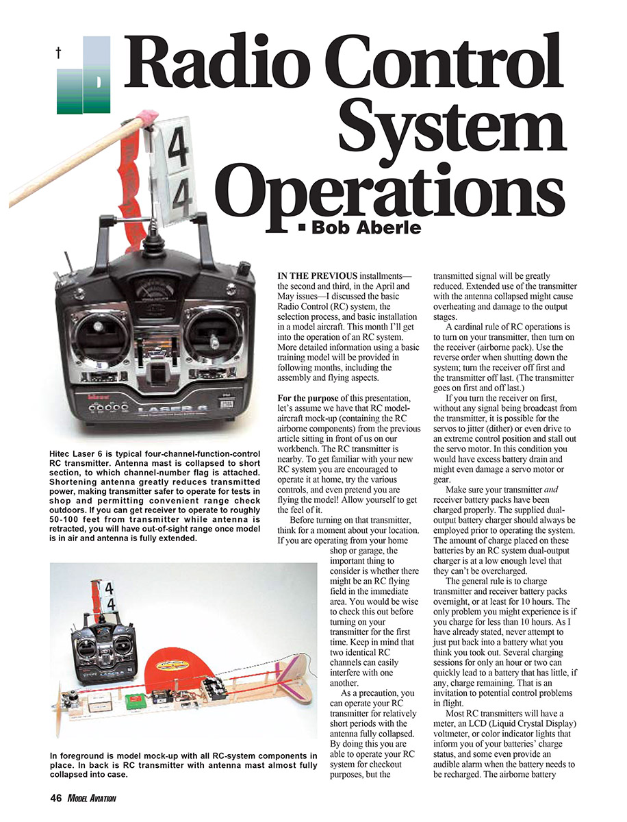
As a precaution, you can operate your RC transmitter for short periods with the antenna fully collapsed. This allows you to checkout the system while greatly reducing transmitted signal strength. Extended use of the transmitter with the antenna collapsed might cause overheating and damage to the output stages.
Power-On Sequence and Batteries
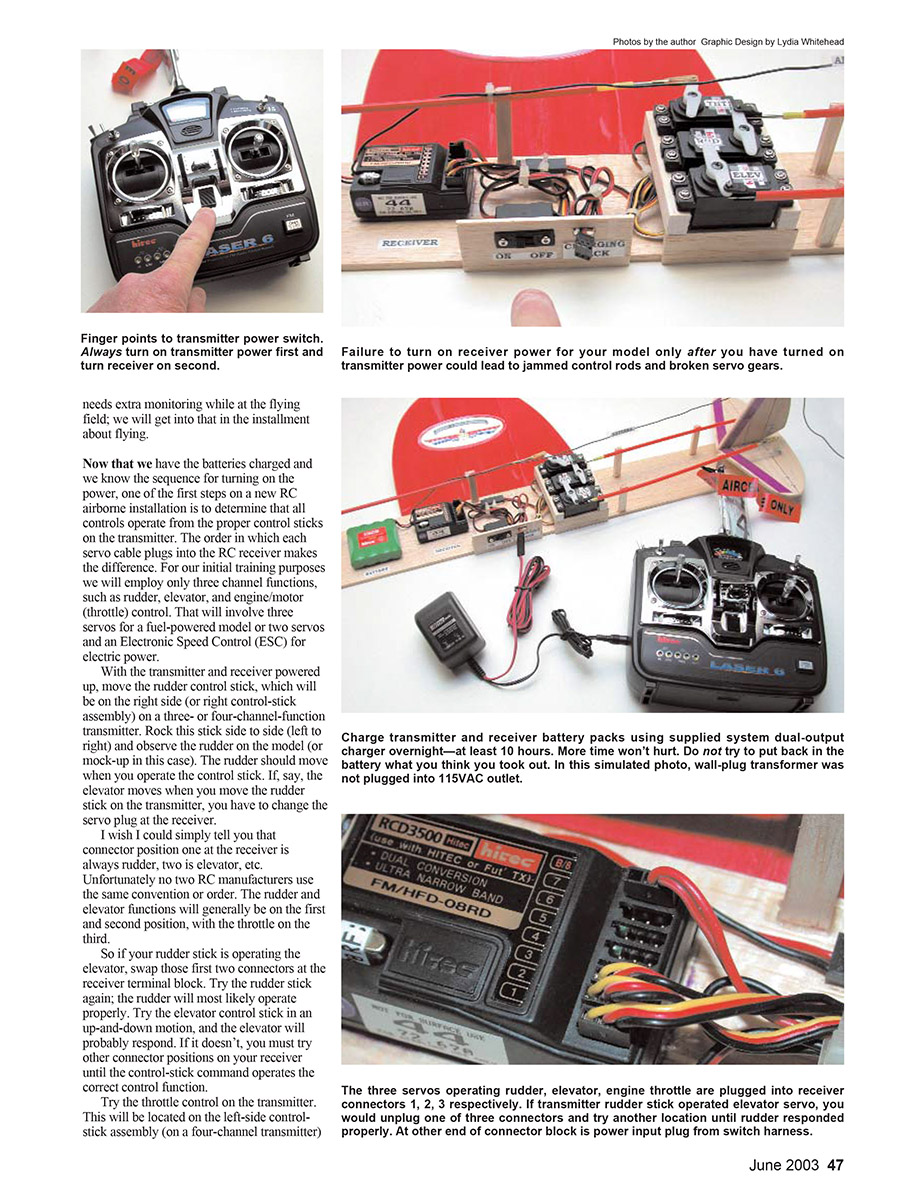
A cardinal rule of RC operations is: turn on your transmitter first, then turn on the receiver (airborne pack). Use the reverse order when shutting down: turn the receiver off first and the transmitter off last. If you turn the receiver on first, with no transmitter signal, servos can jitter (dither) or drive to extreme positions and stall out, causing excess battery drain or servo damage.
Make sure your transmitter and receiver battery packs have been charged properly. Use the supplied dual-output battery charger prior to operating the system. The charge from an RC system dual-output charger is at a low enough level that the packs cannot be overcharged. The general rule is to charge transmitter and receiver packs overnight, or at least for 10 hours. Several short charging sessions (an hour or two) can leave a battery with little or no usable charge, inviting potential control problems in flight.
Most RC transmitters have a meter, an LCD voltmeter, or color indicator lights to inform you of battery charge status; some provide an audible alarm when the battery needs recharging. The airborne battery needs extra monitoring at the flying field; we will address that in a later installment.
Initial Control Check: Channel Assignment
One of the first steps on a new airborne installation is to confirm that all controls operate from the proper control sticks on the transmitter. The order in which each servo cable plugs into the receiver determines this. For initial training, use three channels: rudder, elevator, and throttle (engine/motor). That involves three servos for a glow-powered model or two servos plus an Electronic Speed Control (ESC) for electric power.
With transmitter and receiver powered up, move the rudder control stick (typically on the right side of a three- or four-channel transmitter). Rock the stick side to side and observe the rudder. If the elevator moves when you move the rudder stick, swap the connectors at the receiver until each stick operates the correct control. There is no universal connector convention among manufacturers, though rudder and elevator are often on the first and second positions and throttle on the third.
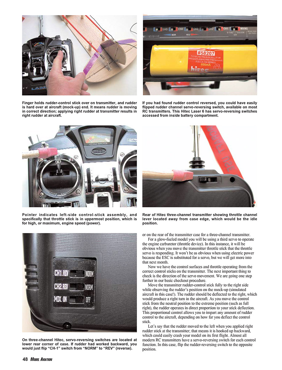
Try the throttle control (usually the left stick on a four-channel transmitter). The throttle should move from idle toward full power when the stick is moved forward, and decrease when moved aft. If the throttle operates in the opposite manner, use the servo-reverse switch on the transmitter or re-install the servo in the horn in the opposite position, or reverse the linkage as required. On some three-channel transmitters the throttle control is a rear-mounted lever; conventionally, moving the lever to the outside of the case is high throttle and moving it toward you is idle.
For glow-fueled models the throttle servo will clearly move the carburetor. For electric-power models the ESC substitutes for a servo and behavior will be discussed in a later installment.
Servo Direction and Reversing
After verifying correct channel assignment, check direction of servo movement. Move the rudder-control stick fully to the right and observe the rudder: it should deflect right. Servo movement is proportional to stick deflection, allowing fine control.
If the rudder moves left when the stick is moved right, flip the rudder reversing switch on the transmitter. Most modern transmitters have a servo-reverse switch for each control function. Verify elevator movement: the elevator should move up when you pull back on the elevator stick.
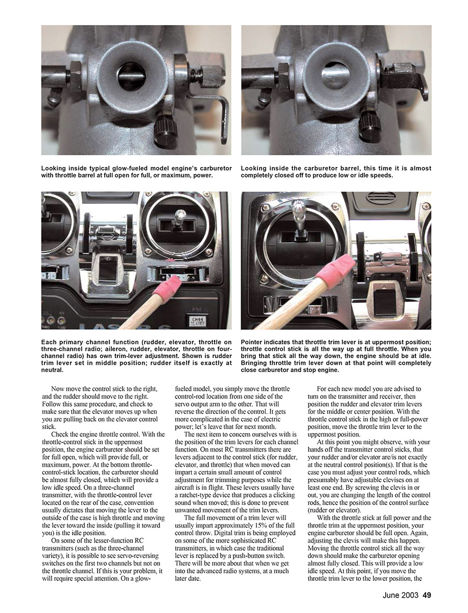
For the throttle, full stick (or lever) should open the carburetor fully for maximum power; idle should be nearly closed. If your transmitter lacks a throttle reversing switch (some basic three-channel units do), on glow-fueled models you can reverse direction by moving the throttle control-rod to the other side of the servo output arm. For electric systems this is more complicated and will be covered later.
Trim Levers and Initial Trim Setup
Trim levers adjust small amounts of control surface deflection for in-flight trimming. They are typically adjacent to each control stick and have a ratchet action to prevent unwanted movement. Full trim lever movement is often about 15% of full control throw. Some advanced transmitters use digital trim via push-buttons.
For each new model, turn on transmitter and receiver and center rudder and elevator trim levers. With the throttle stick at full power, set throttle trim to the uppermost position. If a control surface is not exactly neutral with sticks released, adjust the control rods (adjustable clevises) to achieve neutral positions.
With throttle stick full and throttle trim up, the carburetor should be fully open. With throttle stick down, the carburetor should be nearly closed to provide a low idle; moving the throttle trim to the lower position should stop the engine if set correctly.
Mechanically adjusting the carburetor control linkage can require patience. More advanced transmitters have electronic adjustments that simplify this; for now keep it simple.
Running a Real Engine (Glow) — When Appropriate
If you have a real glow engine, take the model outside and run the engine a few times to fine-tune carburetor settings for various throttle-stick and trim positions. A guest author will cover fueled engine operation and required support equipment (fuel type, pump, starter battery and motor, propeller size, tank size, fuel lines, muffler, etc.) in a future article.
How Much Control Throw?
Manufacturers often provide recommended initial control throws. If not, ask an experienced friend or use these starting values:
- Rudder: ~1 inch each side of neutral
- Elevator: ~1/2 inch each side of neutral
It is better to have a little more than less for the first flight; an instructor will help adjust throws later.
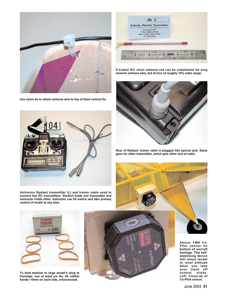
Adjust control throw by changing the clevis attach point on the control horn or the hole used on the servo output arm:
- Move clevis toward the outside of the horn (farther from hinge) to increase throw.
- Move clevis inward (closer to horn root) to decrease throw.
- Similarly on the servo arm: moving from an outside hole closer to the servo hub decreases throw.
Safety Checks and Regular Inspection
Never forget safety checks before the first flight and routinely thereafter:
- Ensure control-surface hinges are properly attached. Physically pull on the control surface to confirm secure attachment.
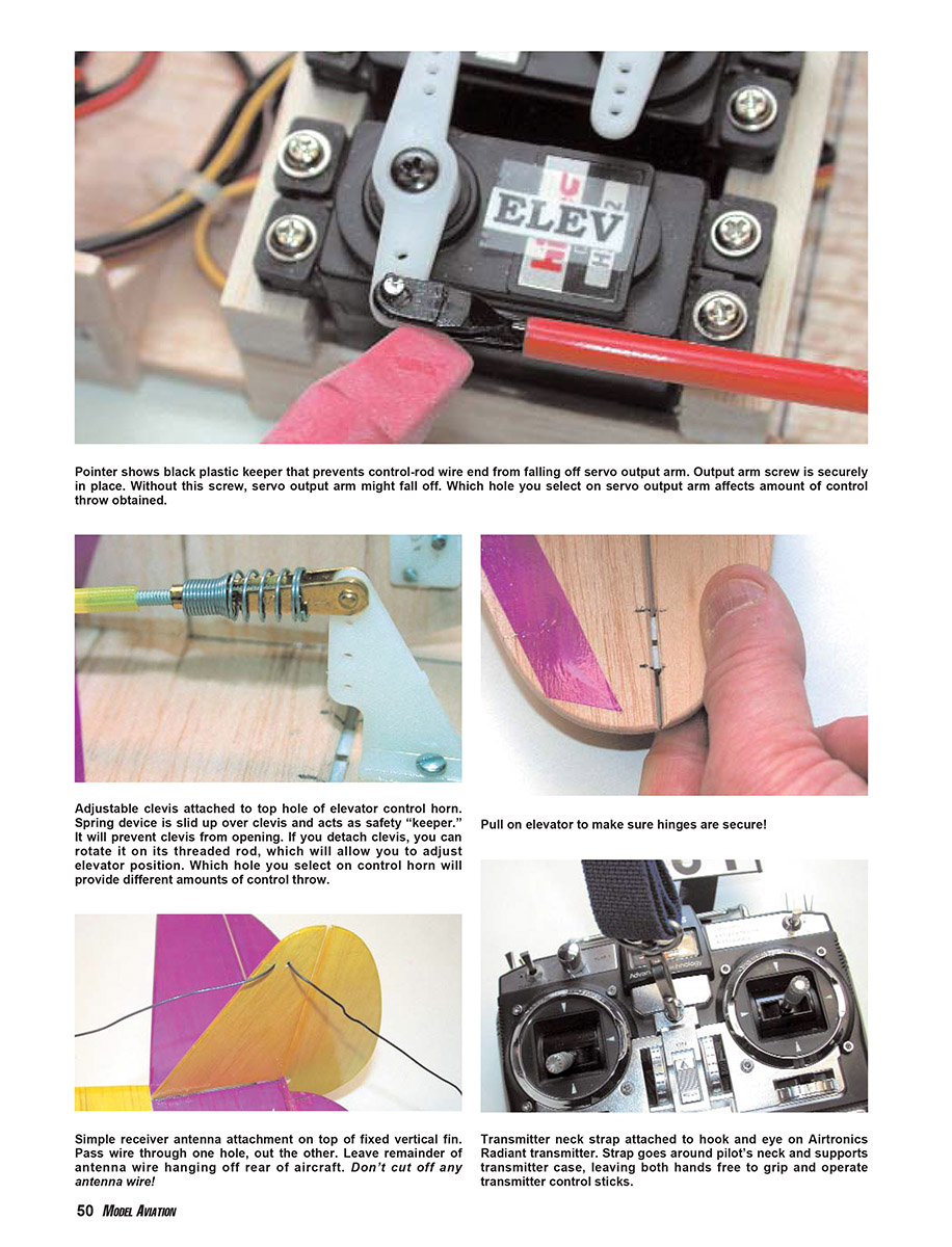
- Verify all control-rod clevises or connectors are locked in place. Use keepers over clevises to prevent separation; use keepers on Z-bend wire ends to prevent dropping off servo arms.
- Confirm the output arm screw is installed. Missing single screws can cause in-flight failures.
- Secure wings properly—trainer-type models often use rubber bands. Use appropriate sizes (No. 64 for average/larger models; No. 33 for smaller park flyers) and use about six rubber bands in a cross pattern (front-left to rear-right and front-right to rear-left). Replace rubber bands each trip to the flying field.
Antenna Routing and Length
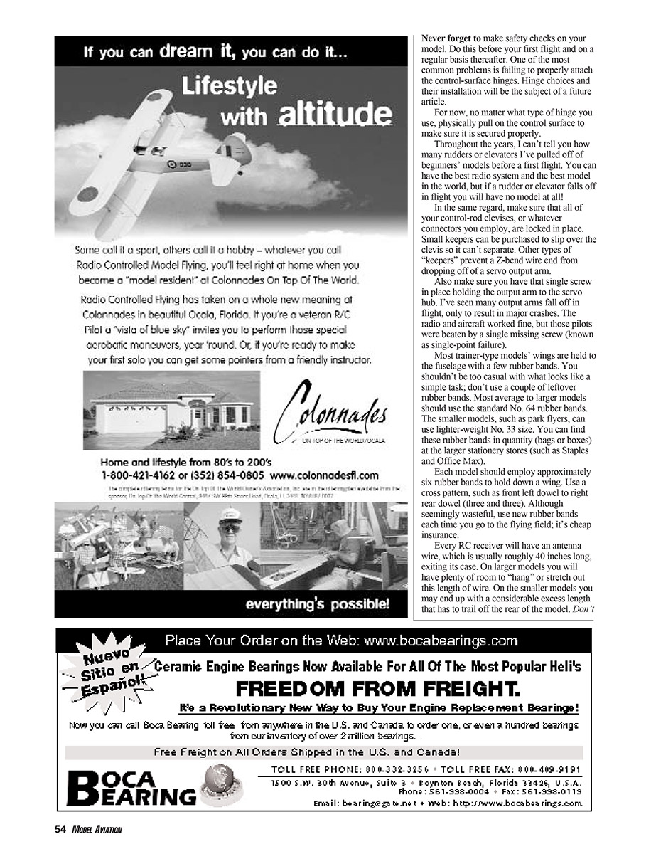
Every receiver has an antenna wire (typically ~40 inches) exiting the case. Do not cut this wire—receiver tuning depends on that length. Shortened antenna rods are available commercially (e.g., Eclectic Electric Necessities / E-Cubed R/C), but they require cutting and soldering to the existing antenna stub. For beginners, stick with the supplied full-length antenna.
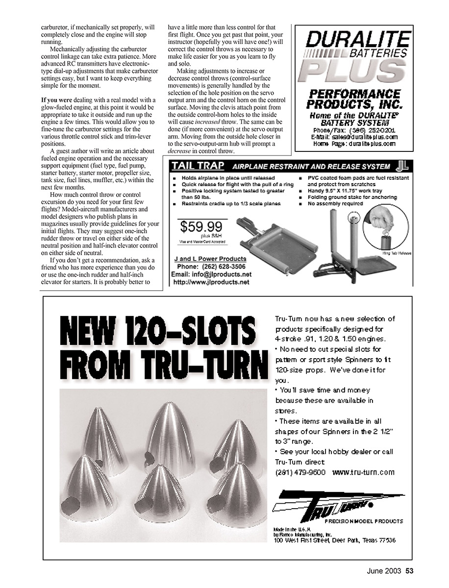
Route the antenna wire clear of noise sources (servo motors, ESCs) to avoid jittery controls or reduced range. Get the antenna wire outside the fuselage as soon as possible and route it up to the top of the vertical fin or stabilizer tip. Drill holes and pass the wire through, but avoid placing tension on the wire or attaching it to moving surfaces (elevator, rudder), which can cause fatigue and breakage.
Range Check
With every new airplane and radio installation you must perform a range check:
- Collapse the transmitter antenna as much as possible (leave a few inches out if it retracts fully).
- Turn on the transmitter first, then the receiver.
- Operate controls and have a friend hold the aircraft while walking away from you. Move control sticks repeatedly and observe control-surface response.
- Note the point where controls become nervous, jittery, or stop responding. Typical acceptable range with the antenna collapsed is roughly 50–100 feet; the manufacturer’s instructions may specify exact values.
If range is very short (e.g., 10 feet), diagnose battery charge, radio faults, or antenna routing problems before flying.
Run the same collapsed-antenna range check with the engine running (for glow) or motor running (for electric) since vibration and electrical noise can affect range.
Hitec Laser 6 is an example of a typical four-channel transmitter. Shortening the antenna greatly reduces transmitted power, making transmitter tests in the shop safer and permitting a convenient outdoor range check. If the receiver operates to roughly 50–100 feet with the antenna retracted, you should have out-of-sight range once the antenna is fully extended.
Transmitter Support, Comfort, and Adjustments
Many four-channel transmitters have a hook-and-eye bracket for a neck strap supplied with the system. Use the strap to support the transmitter and free your fingers to operate both sticks.
Complete transmitter support trays (worn on the neck) are common in Europe. They allow the transmitter to rest in a tray with longer control sticks, offering a full-scale feel. As a new flier, keep it simple and adopt support trays later if desired.
Most transmitters provide adjustments for stick length and spring tension. Refer to your operating manual; these are matters of personal preference.
Trainer Cable, Self-Stabilizing Devices, and Simulators
- Trainer Cable: Many transmitters have trainer jacks. A 6–10 foot trainer cable plugs between two transmitters so an instructor can instantaneously take control via a switch without grabbing the student’s transmitter. It is best when both transmitters are the same brand and preferably the same model.
- Self-Stabilizing Devices: Devices such as the FMA Direct Co-Pilot use sensors (for example, an infrared sensor under the fuselage) to sense and maintain level flight. If the aircraft spirals, releasing the sticks allows the Co-Pilot to return the model to level flight.
- Simulators: PC-based simulators use a transmitter case and sticks to emulate aircraft flight on a monitor. Modern simulators are refined and realistic, making them useful practice tools. Simulators will be covered in a future article.
Preparing for the First Flight
Before your first flight you must:
- Assemble the model (ARF or kit) and install RC equipment.
- Complete all checks described above: power sequence, trims, servo directions, linkage security, hinge security, antenna routing, and range checks (with engine/motor running).
- Get instruction from an experienced pilot or club member. At the flying field, obtain the frequency-control pin for your channel before turning on your transmitter (if using frequency control).
Next month I’ll introduce electric-powered flight—my specialty—and demonstrate selecting an electric ARF, assembling it, operating it, and getting you to that first flight. I’ll also include a simple scratch-built electric sailplane design so you can learn basic building and transfer radio/electric equipment from an ARF to a scratch-built model. Guest authors will cover glow-fueled ARFs, basic building techniques, and covering skills. Other model types (Control Line, Free Flight, rubber power, hand-launched gliders) will also be explored.
Please send questions and suggestions to "From the Ground Up" in care of Bob Hunt, Box 68, Stockertown, PA 18083; E-mail: [email protected].
MA
Bob Aberle
Sources
- RC Systems
- Airtronics Inc.
1185 Stanford Ct. Anaheim CA 92805 (714) 978-1895 [email protected] www.airtronics.net
- Castle Creations
18773 W. 117th St. Olathe KS 66061 (913) 438-6325 Fax: (913) 438-1394 www.castlecreations.com
- FMA Direct
5716A Industry Ln. Frederick MD 21704 (800) 343-2934 Fax: (301) 668-7619 [email protected] www.fmadirect.com
- Futaba Corporation of America
Great Planes Model Distributors Box 9021 Champaign IL 61826-9021 (800) 637-7660 or (217) 398-6300 [email protected] www.futaba-rc.com
- GWS: Balsa Products
122 Jensen Ave. Iselin NJ 08830 (732) 634-6131 www.balsapr.com
- Horizon Hobby Inc.
4105 Fieldstone Rd. Champaign IL 61822 (217) 355-9511 www.horizonhobby.com
- Hitec RCD
12115 Paine St. Poway CA 92064 (858) 748-6948 www.hitecrcd.com
- JR Remote Control
Horizon Hobby Inc.
- Multiplex USA
Hitec RCD and Royal Hobby Distributors 8295 Tujunga Ave. Sun Valley CA 91352 (818) 771-1003 www.multiplexrc.com
- Tower Hobbies
Box 9078 Champaign IL 61826-9078 (800) 637-6050 www.towerhobbies.com
Batteries
- SR Batteries Inc.
Box 287 Bellport NY 11713 (631) 286-0079 Fax: (631) 286-0901 [email protected] www.srbatteries.com
- Batteries America
2211-D Parview Rd. Middleton WI 53562 (800) 308-4805 [email protected] www.batteriesamerica.com
- Maxx Products International
815 Oakwood Rd. Unit D Lake Zurich IL 60047 (847) 438-2233 Ordering only: (800) 416-MAXX (6299) Fax: (847) 438-2898 www.maxxprod.com
Hardware
- Carl Goldberg Products Inc.
Box 818 Oakwood GA 30566 (678) 450-0085 Fax: (770) 532-2163 www.carlgoldbergproducts.com
- Du-Bro Products
Box 815 Wauconda IL 60084 (800) 848-9411 Fax: (847) 526-1604 www.dubro.com
- Sonic-Tronics Inc.
7685 Mill Rd. Elkins Park PA 19027 (215) 635-6520 Fax: (215) 635-4951 [email protected] www.sonictronics.com
- Sullivan Products
1 N. Haven St. Box 5166 Baltimore MD 21224 (410) 732-3500 Fax: (410) 327-7443 www.sullivanproducts.com
Transcribed from original scans by AI. Minor OCR errors may remain.

