
Radio Technique
George M. Myers
HAPPY NEW YEAR! During the 10 years I've been writing "RT", we have tested many radio systems. It has been a rare thing to encounter a defective or unusually poor-performing system, regardless of price. In fact, some of the least expensive sets have often shown the best performances. Likewise, some of the highest-priced sets have produced the worst performances. The overall spread between best and worst has been small, once you discount the two or three real stinkers that we all know about (now).
"Third-order intermodulation interference is the major problem which must be solved." Bill Hershberger
Objective
Reasoning that our previous test method may not have been showing us the most important differences, we retested a representative group of RC systems in an attempt to find a better field test method. Our objective was to find a field test that anyone could perform which would accurately assess performance in the field conditions that we encounter daily.
New Test Method and Test Setup
The New Test Method approximates the condition of taxiing or flying closer to the interferer than to the control transmitter.
Test setup and procedure:
- Place the Control transmitter at a fixed location, held by a person who continuously rocks the aileron control.
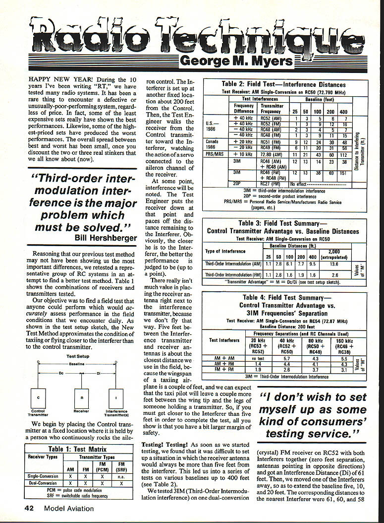
- Set up the Interferer at another fixed location about 200 feet from the Control.
- The Test Engineer walks the receiver from the Control transmitter toward the Interferer, watching the action of a servo connected to the aileron channel of the receiver.
- At the point interference is first noted, the Test Engineer places the receiver down and paces off the distance remaining to the Interferer. The closer the receiver is to the Interferer when interference appears, the better the performance is judged to be (up to a point).
Notes on realistic distances:
- There isn't much value in placing the receiver antenna right next to the interference transmitter, because we don't fly that way. Five feet between interference transmitter and receiver antennas is about the closest distance we use in the field, because the wingspan of a taxiing airplane is a couple of feet and we can expect the taxi pilot will leave a couple more feet between the wing tip and the legs of someone holding a transmitter.
- If you must get closer than five feet to the Interferer in order to complete the test, all you show is a slightly larger margin of safety.
Baseline Tests and Practical Difficulties
As soon as we started testing, we found it difficult to set up situations in which the receiver antenna would always be more than five feet from the Interferer. This led to a series of tests on various baselines up to 400 feet. We tested 3IM (third-order intermodulation) on one dual-conversion (crystal) FM receiver on RC52 with both Interferers together (zero feet separation, antennas pointing in opposite directions) and got an Interference Distance (Di) of 61 feet. Then, we moved one of the Interferers away to extend the baseline by five, 10, and 20 feet. The corresponding distances to the nearest Interferer were 61, 60, and 58 feet.
The tests showed that third-order intermodulation interference can be a major limitation in realistic field conditions. Tables (not included here) summarize field test interference distances and the Control Transmitter advantage versus baseline distances and frequency separations.
Control Transmitter Advantage (M)
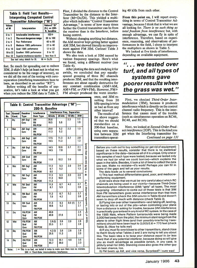
I divided the distance to the Control Transmitter by the distance to the Interferer (M = Dc / Di). This yielded a multiplier which indicates "Control Transmitter Advantage," i.e., how many times farther the Control transmitter can be from the receiver than the Interferer before losing control.
Without changing anything but distance, the AM receiver kept getting better against AM 3IM, but showed literally no improvement against FM 3IM. Curious!
We also examined 3IM caused by various frequency spacings using a different receiver. After plotting and studying the data, we concluded:
- Any equally spaced grouping of three RC channels produces 3IM.
- The resulting interference is about equally destructive for any constant combination (AM+AM, AM+FM, or FM+FM).
- FM+FM always produced the worst interference.
- 3IM resulting from 20 kHz spacing is twice as bad as from any other interval.
These results suggested standardizing on a 200-foot baseline, using zero separation between 3IM transmitters operating 40 kHz from each other.
From this point on I report everything in terms of Control Transmitter Advantage, because that is what we are all looking for. There is no such thing as total freedom from interference; but with enough advantage, we can fly in spite of interference. Based on experience and observations in the field, I chose to interpret the multipliers as shown in the (referenced) Table 5.
"... we tested over turf, and all types of systems gave poorer results when the grass was wet."
Other Interference Types
First, we checked Third-Order Intermodulation (3IM), because it produces interference directly on the control-channel RF. This is the interference that causes most trouble (such as simultaneous operation on RC46, RC48, and RC50).
Next, we looked at Second-Order Product interference (2OP). This is the kind you get when the interfering transmitters produce sum or difference products that fall on the control channel.
Limitations of the Data
Before you rush out to buy something (or get rid of equipment) based on these results, consider that there is no statistical significance in the data—because all of it is unique. Only one or two samples of each type were tested because we tested only what we had on hand or could borrow, which explains gaps in the tables. Besides, it took a lot of time to collect the data you see. Make no mistake—it's work! Perhaps you can fill in some of the gaps and tell us your results.
Conclusions
The data leads us to several conclusions:
- This test method differentiates good, poor, and mediocre-performing equipment.
- All tests show we must be very careful about which RC channels are being used in our vicinity—because Third-Order Intermodulation interference (3IM) affects all types. The most surprising finding is that 3IM from FM transmitters gives more interference than that from AM transmitters and doesn't seem to drop off much with distance.
- Flying low over other transmitters—and taking off, landing, or taxiing into or out of the pits—when controlling your plane from a distance is asking for trouble, because 3IM interference is practically guaranteed in any RC system. For example, in tests of the 1985 Nats where pattern turnarounds were made at 2,000 feet from the pilot, the minimum slant range from the plane to other flight lines (and their possibly interfering transmitters) should have been kept back to 2,000 / 2.6 = 770 feet.
- If you must fly over or close to other transmitters, stand close to them. Keep your distance equal to (or less than) that of any potential interferer, because doing so gives you as much advantage as possible (which, in any case, is pitifully small for 3IM). Standing close also gives the other operator his best chance.
- FM beats up AM, and vice versa. Surprised? I sure was!
Frequency Spacings and Special Cases
- Some frequencies are approximately 455 kHz away from the Control transmitter frequency (for example, Orange/White at 72.400 MHz with RC54 at 72.870 MHz). This could be a problem, but usually it isn't. It wasn't for our test sets, so I left it out of the summary.
- The Personal Radio Service (PRS) and Manufacturers' Radio Service (MRS) channels are 10 kHz away from our RC channels (except the old ones, where they are on top). This is another potential problem.
- We also tested Canadian spacing (adjacent RC channels 20 kHz apart) and U.S. spacing (40 kHz apart). Bear in mind that 3IM is more serious on 20 kHz spacing (e.g., RC50, RC51, RC52).
- Where available, we checked with AM, FM, and FM/PCM as interferers.
Table summaries (not included here) show results by system type. We tested over turf and found all types of systems gave poorer results when the grass was wet; I attempted to reflect that effect in the summary.
The 3IM column is the one to take seriously—none of the RC system types does a good job rejecting it. Most reported glitches and interferences can be traced to 3IM, particularly those associated with approach to landing. Helicopters are particularly susceptible to 3IM due to field setup and the way they are flown in groups.
Today we fly on a 40 kHz spacing; looking at that column shows how the various types are doing in that environment. You'll see that FM sets aren't necessarily an improvement over AM sets, but PCM shows some promise if the 3IM problem can be solved.
For those in Canada, the +20 kHz column shows generally poorer performance, which is to be expected. The +10 kHz column is misleading because our tests used transmitters of approximately equal power; PRS and MRS transmitters can be up to 400 times more powerful than ours, and our radios are vulnerable to them. Yet there haven't been many interference reports traced to them.
Equipment Notes
- I used an old Ace RC Silver Seven (built from a kit) as the AM single-conversion receiver in tests for Tables 2, 3, and 4.
- Test 14 was a Simprop PCM-20.
- I am withholding most product names because I don't wish to set myself up as a consumers' testing service. I will say that most systems tested were 1984 or 1985 models.
- We did what I always do: work something out, test it, then tell you how you can conduct and interpret your own tests.
Policy and Opinion
There has been debate about "What to do in 1988." Some favor splitting the band into an "FM‑Only" preserve and an "Anything Goes" area. No doubt this data will be used on both sides of the argument; some may use it to attack FM. No matter how you slice it, any splitting of the bands is bound to reduce the number of usable channels (due to 3IM problems), which would be counterproductive in discussions with the FCC.
My position remains: keep the whole band open for all forms of modulation. FM must be developed to resist AM, because AMA members won't abandon AM systems until FM sets offer clearly superior performance in rejecting all forms of interference (including engine ignition noise, high-voltage transmission-line corona and arcing, lightning, etc.). The smart short-term move may be to change the AMA Phase‑In Plan to minimize 3IM.
Acknowledgments
I must acknowledge Bob Aberle, who collected equipment and spent hours performing tests and discussing results. Without Bob, I would have stopped writing this column a long time ago. Thanks also to Bill Hershberger, who insisted for years that "3IM is the major problem which must be solved." I finally listened. Thanks to AEC RC for suggesting the 200‑foot baseline; Kraft Systems for providing synthesized RF modules for FM testing; Tower Hobbies for loaning AM transmitters with special crystals; and to the many friends who entrusted us with equipment.
This column may stir controversy. I invite and challenge anyone to disprove our data or conclusions—by putting hard test data on the table.
George M. Myers 70 Froehlich Farm Rd. Hicksville, NY 11801
When responding to advertisers, mention that you read about them in Model Aviation.
Transcribed from original scans by AI. Minor OCR errors may remain.

