
Radio Technique
George M. Myers
There are some rewards to this writing business, and one of them is the opportunity to learn that people really do take your work seriously. Upon returning from this summer's vacation, I found the following letter from Mr. D. H. Reyburn of Merced, Cal., which I have excerpted:
"Shortly after reading your (Sept. '76) column I really crashed an RC plane, and the receiver was found to be completely inoperative. Using your article as a general guide, I checked out the obvious possibilities including the 'shake it and listen for a broken crystal bit,' but no luck.
"Now for the reason for this letter. With the transmitter and the inoperative receiver turned on, I decided to turn on another receiver (same frequency) to check transmitter ground range. Aha, both receivers worked perfectly. Turn off #2 receiver and #1 also dies. I removed the (suspect) crystal from #1 and repeated the test. Again, both worked. In due time, I replaced the defective crystal in #1 and both receivers worked normally. Is this a valid test for broken crystals, and is it worth mentioning in your column? Incidentally, #1 receiver also worked the same way with another system on a different frequency."
Your test is valid, Mr. Reyburn, and I thank you for telling us about it. The local oscillator of any superhetrodyne receiver will radiate a signal from the receiver antenna. This fact is at the root of the recent decision of the FCC to add only 17 channels to the CB spectrum, rather than any of the larger numbers originally proposed. There are so many CB sets, and their oscillator radiations are so strong, that they interfere with one another as well as with TV channel 2, and a host of other radio systems. The 17-channel allocation minimizes the added interference that expanding the CB band will cause.
Back to Mr. Reyburn's test: The signal radiated by #2 receiver was picked up by #1, along with the signal from the transmitter. The difference between them is the normal 455 kHz, which passed right through the intermediate-frequency amplifiers as it should. A normal control signal was decoded and passed to the servos. If a technician had suspected a broken crystal, he would have done the same thing as Mr. Reyburn, except that he would have used a tool called a "grid-dip oscillator" instead of another receiver as the signal source. In all probability, using the GDO, he would have worked much harder than Mr. Reyburn did, because he would have had to adjust the GDO very carefully in order to get results. Thanks again for a good idea! Incidentally, Mr. Reyburn used one of the best tools we have—persistence. When one test doesn't solve the problem, try another.
Downwind Turns
"...Say George, what's the scoop on downwind turns? Are they more dangerous than other turns, or not?" This theme has appeared in several letters recently, prompted no doubt by a circulation-building controversy reported in a non-model aviation magazine.
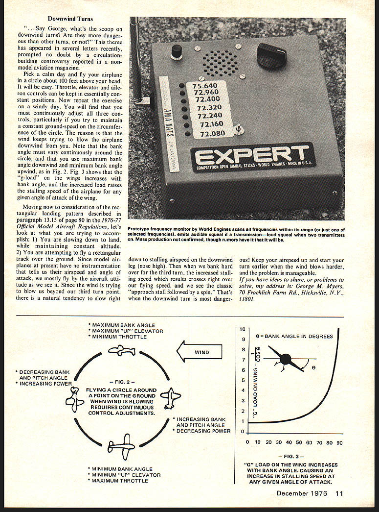
Pick a calm day and fly your airplane in a circle about 100 feet above your head. It will be easy. Throttle, elevator and aileron controls can be kept in essentially constant positions. Now repeat the exercise on a windy day. You will find that you must continuously adjust all three controls, particularly if you try to maintain a constant ground-speed on the circumference of the circle. The reason is that the wind keeps trying to blow the airplane downwind from you. Note that the bank angle must vary continuously around the circle, and that you use maximum bank angle downwind and minimum bank angle upwind, as in Fig. 2. Fig. 3 shows that the "g-load" on the wings increases with bank angle, and the increased load raises the stalling speed of the airplane for any given angle of attack of the wing.
Moving now to consideration of the rectangular landing pattern described in paragraph 13.15 of page 80 in the 1976-77 Official Model Aircraft Regulations, let's look at what you are trying to accomplish: 1) You are slowing down to land, while maintaining constant altitude. 2) You are attempting to fly a rectangular track over the ground. Since model airplanes at present have no instrumentation that tells us their airspeed and angle of attack, we mostly fly by the aircraft's attitude as we see it. Since the wind is trying to blow us beyond our third turn point, there is a natural tendency to slow right down to stalling airspeed on the downwind leg (nose high). Then when we bank hard over for the third turn, the increased stalling speed which results crosses right over our flying speed, and we see the classic "approach stall followed by a spin." That's when the downwind turn is most dangerous. Keep your airspeed up and start your turn earlier when the wind blows harder, and the problem is manageable.
If you have ideas to share, or problems to solve, my address is: George M. Myers, 70 Froehlich Farm Rd., Hicksville, N.Y., 11801.
Transcribed from original scans by AI. Minor OCR errors may remain.

