
Radio Technique
George M. Myers
SAY, GEORGE, what's the difference between positive and negative pulses, and which is better? How can I tell what kind my RC system has, and what is a pulse used for anyway? This about summarizes the questions on the subject that are most frequently asked.
To begin with, neither is better, and the difference is simply in the direction that the electrons are flowing in the control signal wire. However, you can't mix positive- and negative-pulse servos without using a pulse inverter (see May 1977 column).
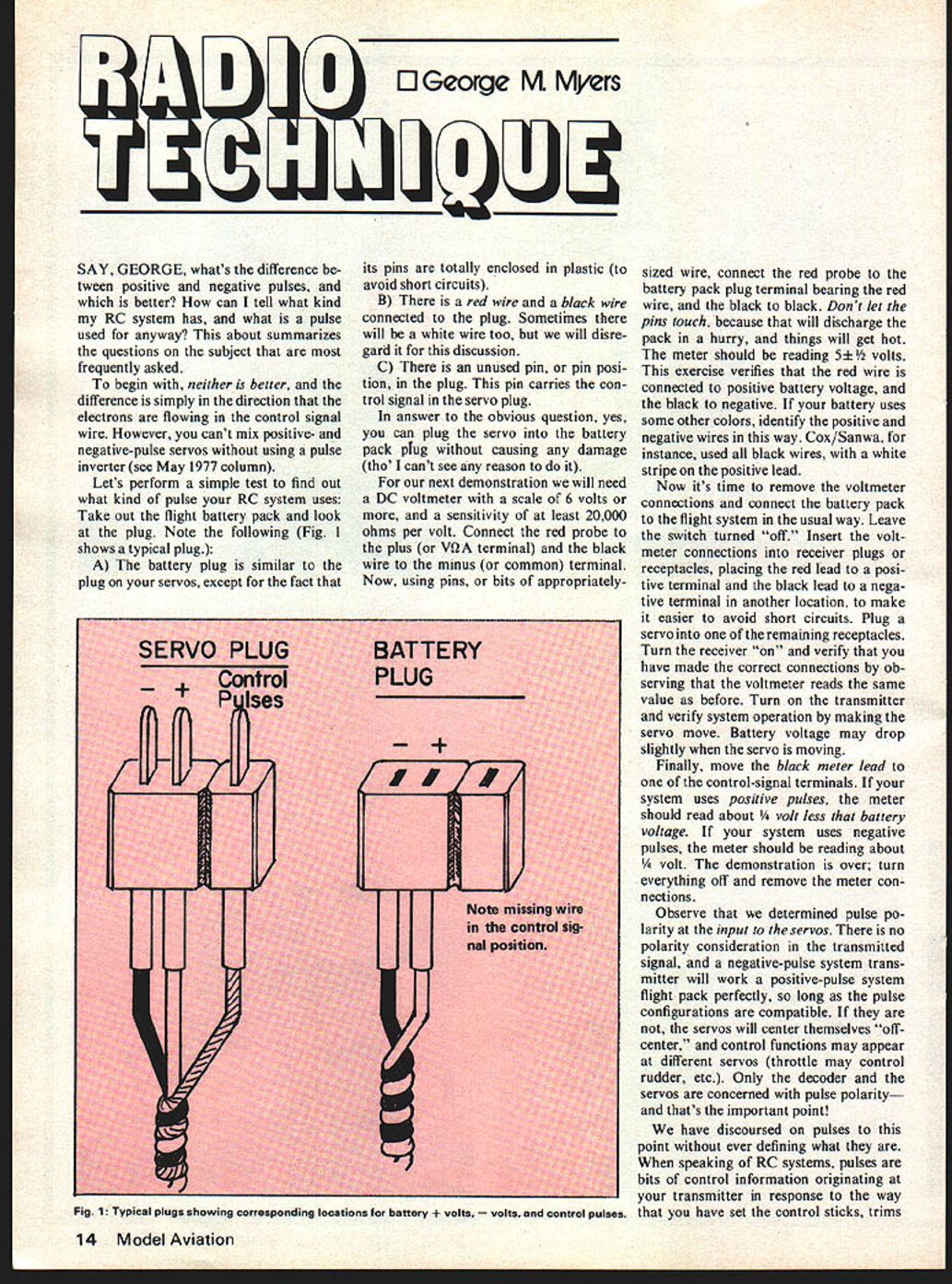
Let's perform a simple test to find out what kind of pulse your RC system uses: Take out the flight battery pack and look at the plug. Note the following (Fig. 1 shows a typical plug.):
A) The battery plug is similar to the plug on your servos, except for the fact that its pins are totally enclosed in plastic (to avoid short circuits).
B) There is a red wire and a black wire connected to the plug. Sometimes there will be a white wire too, but we will disregard it for this discussion.
C) There is an unused pin, or pin position, in the plug. This pin carries the control signal in the servo plug.
In answer to the obvious question, yes, you can plug the servo into the battery pack plug without causing any damage (tho' I can't see any reason to do it).
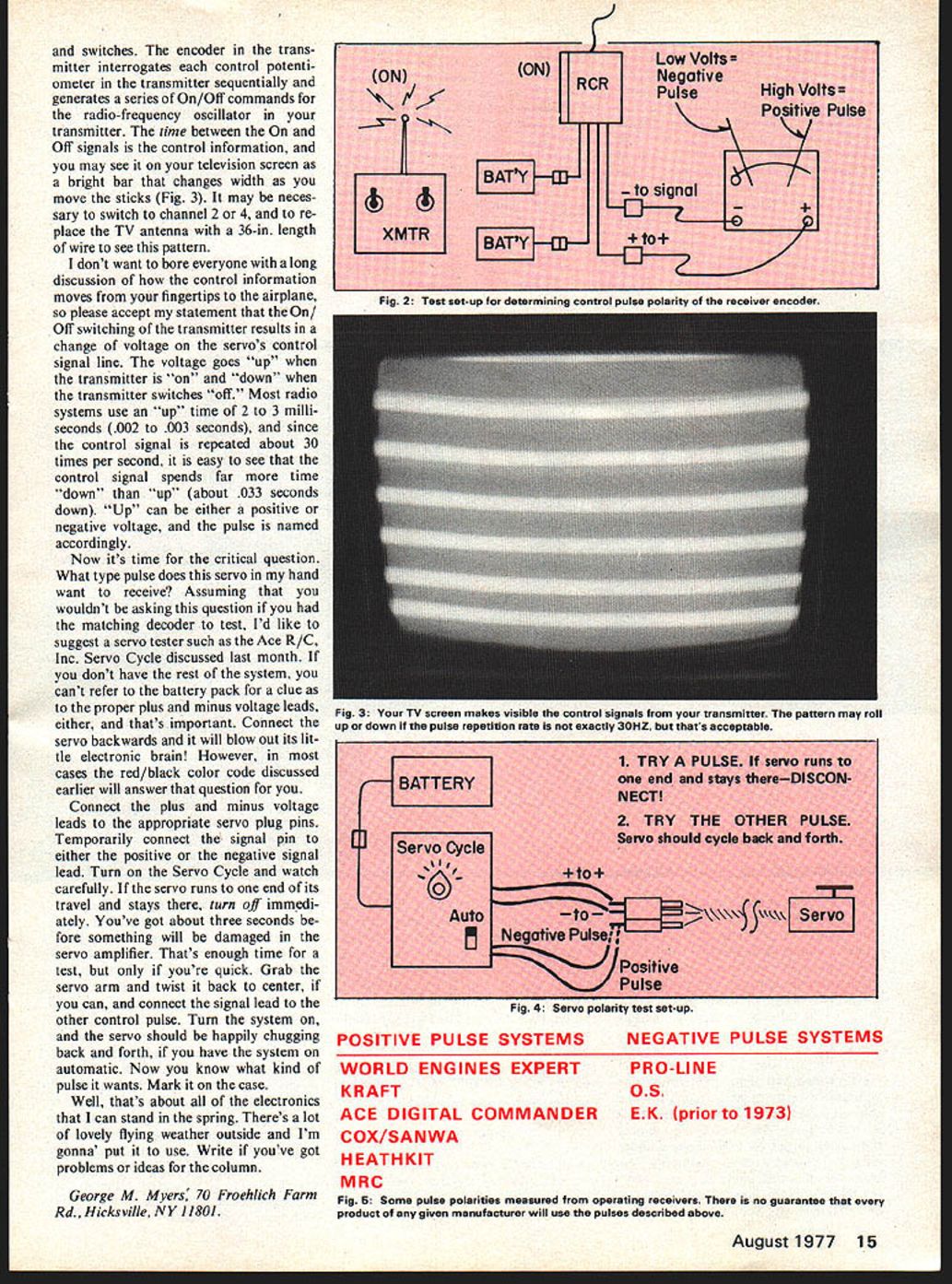
For our next demonstration we will need a DC voltmeter with a scale of 6 volts or more, and a sensitivity of at least 20,000 ohms per volt. Connect the red probe to the plus (or V+) terminal and the black wire to the minus (or common) terminal. Now, using pins, or bits of appropriately sized wire, connect the red probe to the battery pack plug terminal bearing the red wire, and the black to the black. Don't let the pins touch, because that will discharge the pack in a hurry, and things will get hot. The meter should be reading 5-1/2 volts. This exercise verifies that the red wire is connected to positive battery voltage, and the black to negative. If your battery uses some other colors, identify the positive and negative wires in this way. Cox/Sanwa, for instance, used all black wires, with a white stripe on the positive lead.
Now it's time to remove the voltmeter connections and connect the battery pack to the flight system in the usual way. Leave the switch turned "off." Insert the voltmeter connections into receiver plugs or receptacles, placing the red lead to a positive terminal and the black lead to a negative terminal in another location, to make it easier to avoid short circuits. Plug a servo into one of the remaining receptacles. Turn the receiver "on" and verify that you have made the correct connections by observing that the voltmeter reads the same value as before. Turn on the transmitter and verify system operation by making the servo move. Battery voltage may drop slightly when the servo is moving.
Finally, move the black meter lead to one of the control-signal terminals. If your system uses positive pulses, the meter should read about 1/4 volt less than battery voltage. If your system uses negative pulses, the meter should be reading about 1/4 volt. The demonstration is over; turn everything off and remove the meter connections.
Observe that we determined pulse polarity at the input to the servos. There is no polarity consideration in the transmitted signal, and a negative-pulse system transmitter will work a positive-pulse system flight pack perfectly, so long as the pulse configurations are compatible. If they are not, the servos will center themselves "off-center," and control functions may appear at different servos (throttle may control rudder, etc.). Only the decoder and the servos are concerned with pulse polarity — and that's the important point!
We have discoursed on pulses to this point without ever defining what they are. When speaking of RC systems, pulses are bits of control information originating at your transmitter in response to the way that you have set the control sticks, trims and switches. The encoder in the transmitter interrogates each control potentiometer in the transmitter sequentially and generates a series of On/Off commands for the radio-frequency oscillator in your transmitter. The time between the On and Off signals is the control information, and you may see it on your television screen as a bright bar that changes width as you move the sticks (Fig. 3). It may be necessary to switch to channel 2 or 4, and to replace the TV antenna with a 36-in. length of wire to see this pattern.
I don't want to bore everyone with a long discussion of how the control information moves from your fingertips to the airplane, so please accept my statement that the On/Off switching of the transmitter results in a change of voltage on the servo's control signal line. The voltage goes "up" when the transmitter is "on" and "down" when the transmitter switches "off." Most radio systems use an "up" time of 2 to 3 milliseconds (.002 to .003 seconds), and since the control signal is repeated about 30 times per second, it is easy to see that the control signal spends far more time "down" than "up" (about .033 seconds down). "Up" can be either a positive or negative voltage, and the pulse is named accordingly.
Now it's time for the critical question. What type pulse does this servo in my hand want to receive? Assuming that you wouldn't be asking this question if you had the matching decoder to test, I'd like to suggest a servo tester such as the Ace R/C, Inc. Servo Cycle discussed last month. If you don't have the rest of the system, you can't refer to the battery pack for a clue as to the proper plus and minus voltage leads, either, and that's important. Connect the servo backwards and it will blow out its little electronic brain! However, in most cases the red/black color code discussed earlier will answer that question for you.
Connect the plus and minus voltage leads to the appropriate servo plug pins. Temporarily connect the signal pin to either the positive or the negative signal lead. Turn on the Servo Cycle and watch carefully. If the servo runs to one end of its travel and stays there, turn off immediately. You've got about three seconds before something will be damaged in the servo amplifier. That's enough time for a test, but only if you're quick. Grab the servo arm and twist it back to center, if you can, and connect the signal lead to the other control pulse. Turn the system on, and the servo should be happily chugging back and forth, if you have the system on automatic. Now you know what kind of pulse it wants. Mark it on the case.
Well, that's about all of the electronics that I can stand in the spring. There's a lot of lovely flying weather outside and I'm gonna put it to use. Write if you've got problems or ideas for the column.
George M. Myers, 70 Froehlich Farm Rd., Hicksville, NY 11801.
POSITIVE PULSE SYSTEMS
- WORLD ENGINES
- KRAFT
- ACE DIGITAL COMMANDER
- COX/SANWA
- HEATHKIT
- MRC
NEGATIVE PULSE SYSTEMS
- EXPERT
- PRO-LINE
- O.S.
- E.K. (prior to 1973)
Transcribed from original scans by AI. Minor OCR errors may remain.

