

RC Eindecker
Dick Sarpolus
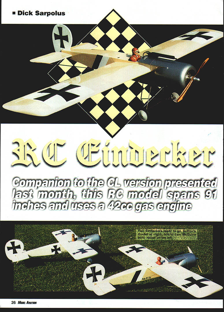
Companion to the CL version presented last month, this RC model spans 91 inches and uses a 42cc gas engine.
Designing and scratch-building an aircraft project is a big part of the hobby's fun for me, and through the years I've done original designs and stand-off or semiscale types, military and commercial aircraft.
The one type I hadn't done before was World War I aircraft, despite their widespread appeal. This is probably because I prefer all of my aircraft to be fully aerobatic-capable and easy to build and fly; it's tough to do a World War I aircraft and get these characteristics.
WW I airplanes certainly weren't intended to do today's maneuvers; their designers had enough problems getting them to stay together in the air and withstand the combat maneuvers the ace pilots of the time were dreaming up. With the airfoils, materials, and power plants available then, the aircraft designers did quite a job, but that's just not the type of flying machine I want to relax and have fun with.
The appeal of the World War I types is hard to resist; my local club has members who have annually made the trip to Rhinebeck for many years, and they have so much fun with their First War aircraft that I wanted to build one of that type myself.
I picked the Eindecker because it is one of the very few World War I monoplanes; another good choice I believe would be the Junkers series of monoplanes, and I plan to do one of those.
I planned to work with a gas-engine power plant—the Cheetah/Quadra/US Engines 42 type—because I know what aircraft "numbers" work well with their power. But the airplane would have to be easy to build, with a foam-core wing, a thick, symmetrical airfoil, and a layout that I knew would produce the kind of flying I preferred.
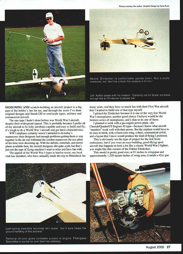
This is obviously not the type of project for the real scale enthusiast; but if you want an easy-building, good-flying sport aircraft that happens to look a lot like a classic World War I fighter, you might like this version of the Fokker Eindecker.
This model is pretty good size; at 91 inches in wingspan and approximately 1,350 square inches of wing area, it needs a 42cc gas engine. If you prefer glow, I'm sure the larger SuperTigres would do well.
It's not a lightweight, but at 16 pounds the wing loading is pretty low at 28 ounces per square foot, providing lively performance and easy handling.
Although this sporty Eindecker has modern aerodynamics with a thick symmetrical airfoil, I tried to keep the outline shapes and overall characteristics of the original World War I design, along with some of the features we like in today's models. Tip ailerons, a large rudder, and a steerable tailwheel enable good maneuverability and easy ground handling.
I use standard-size servos for this size aircraft, with one servo on each aileron, one on each elevator, and two more for rudder and throttle. A smoke system would be a nice addition. A reasonably authentic finish, the right insignia, a pilot figure in the cockpit, and a machine gun help to achieve the classic Eindecker appearance.
The test flights showed that the design "worked." It looks like an Eindecker to me and flies like I want a sporty gas-engined model to fly. Not for everyone maybe, but if you're a relaxed sport flier and want to have a World War I fighter in the hangar, consider this aircraft.
If the appearance of an Eindecker performing today's aerobatic maneuvers would upset you, I suggest you might lighten up and enjoy the sight.
CONSTRUCTION
Three-views used for the original plans were obtained from Bob Banka's Scale Model Research (3114 Yukon Ave., Costa Mesa CA 92626).
Wing
Construction starts with the preparation of the foam wing cores. I consider foam-core cutting a basic model aircraft scratch-building technique, requiring a reasonable investment in shop equipment. It's a procedure that has been covered many times in the model magazines.
The know-how is probably available in most clubs; if not, there are custom foam-core cutters who advertise in the model magazines, such as Dynamic Balsa and Hobby Supply Inc. (Box 107, Lenore IL 71332; Tel.: (815) 586-2272). This will make building the Eindecker a pretty easy project.
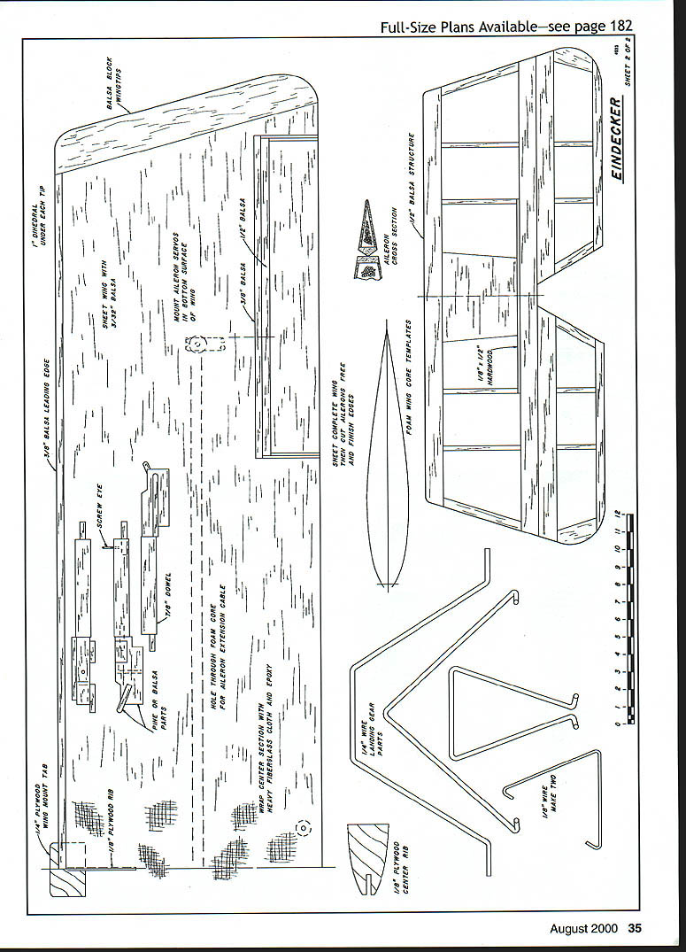
Patterns for the foam-cutting templates are shown on the plans; I make my templates from 1/8" plywood.
The only work to do on the wing cores before sheeting them is to sand the root ends at a slight angle for the wing dihedral, and to trim back the root ends at the leading edge to accept the plywood partial rib, which reinforces the wing-mounting tongue. Cut off the outboard tips at the angle shown on the plans. If the cores are rough, some sanding with fine sandpaper will ensure a better bond with the sheeting.
The wing panels are sheeted with 3/32" medium balsa, edge-glued as necessary for lengths and width. I prefer aliphatic resin woodworking glues for the edge-gluing because that glue is easier to sand for a smooth joint.
The difficult part of edge-gluing the balsa for sheeting is getting a good fit between the individual sheets; most balsa won't have good straight edges. I use a long sanding straightedge made from a piece of aluminum right-angle stock with sandpaper glued on. On a badly warped piece of balsa, you can cut a new straight edge with a long steel ruler and a sharp modeling knife.
The separate sheets are taped together with masking tape to make up the width needed; then flip the wood over, open the taped joints one at a time over the edge of the workbench, and apply the glue to the edges of the wood. With the sheeting flat on the bench, scrape the excess glue off each joint with a putty knife and weight the wood until the glue dries.
Remove the masking tape and use the taped side as the outer surface of the sheeting. I sand the inside surface of the sheeting with rough sandpaper to speed up the work, and use fine sandpaper to finish off the outer surface.
I recommend Dave Brown's Southern Sorghum contact cement to apply the sheeting; I've used it for many years, and it works. Alternatives are thinly spread epoxy, spray can cements, or whatever you prefer; but be sure it works.
With the cores sheeted top and bottom, trim off the leading edge overhang and block-sand it square. Add an oversized leading-edge strip. I use 5-minute epoxy for most of this work to speed things up. Plane and sand the leading edge to shape.
The trailing edge is trimmed off close to the foam core, and rounded off. Balsa tip blocks are added, and shaped and sanded to shape. Then the ailerons are cut free from the sheeting wing panels and trimmed to allow for the balsa edging on both the wing panels and the ailerons, which is epoxied in place and sanded to shape.
Hinge the ailerons along their centerline, using large, sturdy, freely moving hinges of the type you prefer. Keep the gap between the ailerons and wing as tight as possible while still permitting full movement of the ailerons. Don't glue the hinges in place yet; that will be done later, after the covering has been applied.
Recesses are cut into the bottom wing surface for the aileron servo mounting. Epoxy plywood mounting pieces into position in the wing to suit your servos, having the servos protrude from the wing surface just far enough for hookup of the aileron pushrods. I used to bury the aileron servos completely inside the wing with removable hatches for access, but it's much easier to just leave them exposed.
A hole is needed through the foam cores from the root to the aileron servo location for the servo extension cable. To melt the tunnel, I heat the end of a piece of metal rod with a propane torch and push the hot end through the foam; I hope your aim is good.
Where the wing hold-down bolts will be located, insert dowel sections or hardwood blocks flush with the sheeted wing panels before the fiberglass cloth and epoxy is added.
Block up the tips of the wing panels to join the wing at the proper dihedral angle; I use approximately one inch dihedral under each tip.
Butt-glue the wing halves together, then wrap the center joint of the wing with heavy fiberglass cloth and epoxy. Use double layers of cloth in the center. I've been using nine-inch-wide strips of glass cloth, overlapped in the center to give a five-inch-wide double layer.
I brush on a coat of epoxy, position the fiberglass cloth, and brush on additional epoxy to be sure the cloth is saturated. For a good, smooth appearance without too much sanding or extra weight, I squeegee off excess epoxy, leaving enough so the cloth is saturated for strength, but is smooth and level.
The plywood wing mounting tab is used at the leading edge to position and retain the wing; cut through the fiberglass cloth to add the plywood tab, or install it first and cut the cloth as you apply it. With the tab in the wing, the contact area of the fuselage bulkhead retaining the wing mount can be trimmed or shimmed as necessary to get the correct wing-to-fuselage fit.
Fuselage
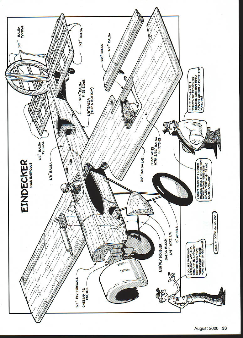
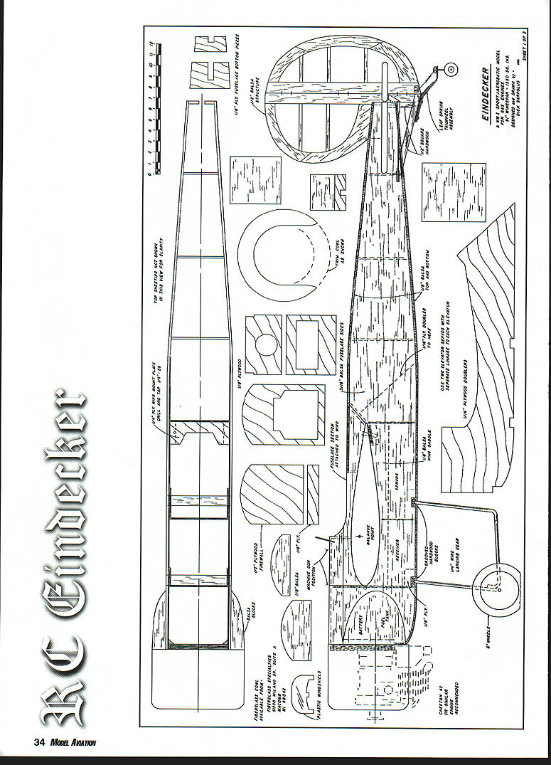
Select firm-to-hard 3/32" balsa for the sides, edge-gluing and splicing as necessary to get the size required. Glue the 1/16" plywood doublers, 1/8" plywood landing gear block doublers, balsa wing saddle doublers, and the stab saddle doublers to the fuselage sides.
The firewall is in two sections, with the bottom piece set back for muffler clearance. The top section is 1/2" plywood (two pieces of 1/4" epoxied together) and the bottom piece is 1/8" plywood. If you use a different type of engine and muffler setup, you might want to go to a one-piece firewall.
With one fuselage side flat on the workbench, add the firewall and the next three bulkheads, installing them perpendicular to the side. Glue the second side to those bulkheads and firewall; the sides are parallel from the firewall to the wing trailing edge position.
Add triangle stock and fiberglass cloth behind the firewall to reinforce its joint with the sides; I also put several small screws into the firewall through the fuselage sides.
With the fuselage up off the workbench, add the grooved hardwood landing gear mounts and the 1/4" plywood wing bolt plate. I back up this plate with small pieces of 1/8" plywood where the wing retaining bolts will go, to have more material for threading.
Pull the tail end together and install the rear bulkheads; note that the fuselage is left fairly wide at the back end. Some 1/8" plywood parts at the rear end of the fuselage reinforce the installation of the 1/2" hardwood pieces, which serve as the base for the leaf-spring tailwheel assembly. Not scale, but it sure makes for easy ground handling.
Drill the firewall to suit the engine mounting; I use 10-32 Allen bolts with blind nuts installed in the rear of the plywood firewall. When the holes are put through the firewall for the fuel line, throttle linkage, and possibly ignition system wiring, the top and bottom nose section planking can be added.
I epoxy the inside of the nose section to protect against any fuel tank leaks. I leave off the rear fuselage bottom planking until the tail surfaces are added, so I can cut holes in the bulkheads for the elevator and rudder pushrods.
The fuselage forward top sheeting is glued on, and the two balsa side pieces cut to fit. I used the round fiberglass cowl to mark the two side blocks for shaping, and shaped and rounded them before gluing them in place.
Tail Surfaces
These are built-up open structures, made flat on the workbench. I used hard balsa for the stab and fin edges to be sure of adequate strength. Cut the slots or drill the holes along the centerlines of the surfaces for whatever hinge type you're using, and notch the control surfaces as required to permit a close fit of the surfaces to the main structures, allowing proper movement.
I use 1/4" plywood for control-horn mounting, recessing and epoxying the plywood into the elevators and rudder. The horns are mounted with self-tapping screws.
Assembly
I mount the wing to the fuselage next, adjusting the fit of the wing mounting tab through the fuselage bulkhead if necessary, and drill and tap the wing mount for the 1/4-20 nylon bolts that hold the wing in place.
After the wing has been mounted, I add the horizontal stabilizer, aligning it with the wing. The vertical fin is then added, perpendicular to the stabilizer. I had the rudder pushrod exiting through the end of the fuselage, above the stab. Of course, the two elevator pushrods exit beneath the stab. The usual nylon horns and springs are used to couple the rudder to the tailwheel for steering.
With the wing bolted in place, the fuselage top center structure is built onto the wing. Glue the side pieces to the wing, trimming them to fit, followed by the bulkheads for this section. The forward curved top sheeting is added, and the flat rear section sheeting; I have two holes in that sheeting for access to the wing hold-down bolts.
The pilot figure is trimmed later to fit against the cockpit sides and the windscreen glued in place. I used a 1/16" ply floor in the cockpit area to form the seat and mount the instrument panel. The canopy is formed from clear heat-shrink plastic. The engine is an OS LA .25 with a 10x6 prop, mounted on a 1/8" ply plate and held with two rubber bands. The fuel tank is 14 oz.
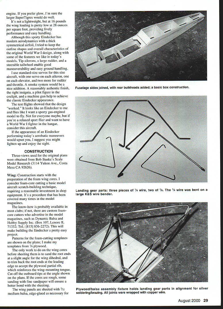
I used a heavy-duty K&S wire bender, along with a solid vise and hammer to get the wire bending done, cutting the wire with a Dremel® tool and cutoff wheel. Adjust the bends so the wire parts that overlap each other for joining are parallel as possible.
Bending 1/4" wire isn't easy, but the thing I disliked most is the random breaking of the wire during bending. I didn't want to get into preheating and somehow retempering the wire, so I just kept bending parts until I got what I needed.
I suppose that a sheet-aluminum landing gear could be bolted to the bottom of the fuselage, but I think it would look terrible. The wire bending is worth it for the scale appearance.
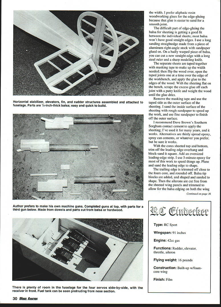
The plastic wheelshield is edged with small black fuel tubing, which adds to the appearance, along with the machine gun. Williams Bros. makes a very detailed machine gun in the right size, but I made a less-detailed more rugged version from some scrap pine and dowels.
Finish
There isn't much variety to choose from for an Eindecker color scheme; some sort of cream or light tan overall with white fin/rudder and white backing for the German WW I crosses. I did see a mention in one Eindecker reference that Max Immelmann's airplane had a diagonal black-and-white stripe behind the cockpit, so I went with that.
The lettering I used and the black cross insignias were done by Vinylwrite Custom Lettering (16043 Tulsa St., Granada Hills CA 91344)—a very friendly and helpful outfit.
I am really happy with this Eindecker. Back around 1968 I built a Nick Ziroli Eindecker with an Enya .45, and had a good deal of fun with it for some years. Thirty years later, this big gas-engined model brings back good memories of that Ziroli Eindecker. I like the size of this one, the gas-engine sound, and its '90s aerobatic capability.
Scale or not, I enjoy seeing the Eindecker in a low, inverted pass across the field. Have fun! MA
Dick Sarpoulas 32 Alameda Ct. Shrewsbury, NJ 07702
Transcribed from original scans by AI. Minor OCR errors may remain.

