
RADIO CONTROL ELECTRICS
Bob Kopski, 25 West End Dr., Lansdale PA 19446
THIS COLUMN will cover a Sport Speed Control (SSC) part-number change, one SSC "tune-up" note, the evolving Astro 110D and a strong advisory, my new "park flier," and the delayed soldering packs information.
Sport Speed Control (SSC) parts and reader input
Recent reader input: Readers have advised me of two now-obsolete parts as used in the "Sport Speed Control" (MA, 9-10/99): adjustable trimmer resistors R6 (100 Ohms) and R9 (100 KOhms). The published Digi-Key catalog numbers are 36C12-ND and 36C15-ND respectively.
The replacement-part numbers are 36G12-ND and 36G15-ND, in that order.
These are Panasonic units, and the new ones appear dimensionally identical to those in the Digi-Key catalog descriptions. The new resistors differ because they are adjustable from both sides, instead of just from the top side—a matter of no consequence in the SSC.
Based on all information available, these are direct replacements.
According to Digi-Key, other direct substitutions are the Bournes 3306P-101-ND and 3306-104-ND. However, these are slightly larger than the above-named items, and will protrude approximately 1 mm from the SSC board's edge. Electrically, they should work perfectly. The cost difference is pennies.
Other reader input about the SSC deals with the preceding adjustable resistors lacking adequate adjustment range to set the low and high throttle points.
I haven't gotten to the bottom of this yet, but it probably has nothing to do with the SSC and is more likely associated with the throttle stick behavior. That would be the case if the throttle range has been reprogrammed for some other reason. This possibility was discussed in the SSC article (September 1999 MA, page 84).
If this sounds like a problem you have, reaffirm the proper throttle range of your programmable transmitter.
Some programmable transmitters allow settings to be returned to their default, which results in stick behavior similar to that of nonprogrammable transmitters.
Until now, I haven't experienced SSC adjustments that did not work as described in the article. If you experience this (or any other problem), be sure to write. I will work hard to help you.
Astro 110D chargers — evolution and a safety advisory
Regular readers know that one of my favorite E-products of all time is the Astro 110D, a one- through 18-cell charger. From the day in 1995 when I got a sample of the then-new product, until today when I have three, I have preferred this item.
The 110D has steadily evolved in performance and features so much that the earliest, latest, and even some in-between models function differently.
For this discussion, I'll refer to my three 110D chargers as units "A," "B," and "C," indicating the chronological order in which I got them. Acquisitions were in roughly equally spaced years. The inspection sticker dates inside the units are 7/95, 9/95, and 11/99.
Each unit is different in some way; no two panels or instruction sheets are the same.
There is a potentially critical matter with the 110D, and it's the reason I bought my third charger. Despite years of use, I did not know that earlier 110D panels were electrically "hot." Unfortunately, I found out the hard (and costly) way.
I dropped an exposed positive lead from another charger so that it brushed by a panel screw on my A unit. There was a brief spark, and I didn't know until later, but this killed the A charger.
I determined that the panel of the A unit is connected to the negative input power wire. This electrical path is via the physical contact of the LCD (Liquid Crystal Display) housing that presses against the inside rear of the panel.
From this interface, the path follows printed circuit wiring and ultimately reaches the input negative lead. The brief contact and spark completely burned at least one such PC path and did further damage. I could repair the burned land, but I could not find whatever else was damaged.
(This hurt because it's a lost charger, and because it's an "old personal friend"; it was programmed to read out "Property of Bob Kopski" on the LCD when first powered up.)
I promptly purchased another 110D, unit C, then I checked units B and C for any electrical panel path. The B charger had the same problem as A, but unit C did not.
I disassembled B, and put a double layer of PVC (black polyvinyl chloride) electrical tape around the inside panel readout cutout; this way, the LCD assembly could not electrically touch the charger panel.
Check out your own 110Ds (and other chargers) for this condition. Use an ohmmeter and invoke the lowest and higher ranges, and probe among all four input and output connections and a bare spot on the panel.
The panel has an insulating coating, except for screw heads and the exposed metal around the display cutout.
You should read "infinity" on the meter. If you read a low path resistance between the panel and any input/output connection, you can do as I did. If you don't want to go inside your charger, at least you'll be aware of the potential for a costly accident.
Van installation and operational notes
My two 110Ds are semipermanently installed in the rear of my minivan (July 1997 MA). They are wired into the van's power via Semos connectors, so both are modified to include a power switch on the front panel. I also installed an LED "on" indicator.
I extended the output leads to roughly eight feet of ordinary lamp cord. Now I can easily reach my electrics on the ground outside the rear of the minivan.
And both 110D chargers use my End-Of-Charge Beeper (March 1997 MA), which is one of the most popular items ever included in this column.
Unit-to-unit differences and performance
With the 110D chargers wired into my van, I've started and stopped the engine many, many times while the chargers were in operation. Unit B always performs solidly, despite the severe electrical disturbance associated with the engine start/stop.
If unit C is operating when I start the car, it drops out and I have to reset it. Then the C charger works with the engine running, and it continues to do so thereafter—even when I shut the ignition off.
I looked into this further, and I determined that the newest unit drops out (stops charging) when input voltage drops somewhere below 11 volts. This can easily happen to car voltage during startup, and is the most likely explanation for C's dropout.
I've also interpreted this as a possible attempt by Astro to protect the charger and the vehicle.
In constant current chargers such as the 110D, the input current from the source varies as needed, enabling the charger to continually supply the selected current to your model's motor pack.
If the input voltage falls, as it would with a weak car battery, the input current rises to "make up" for the falling source voltage; the charger input behaves like a variable resistance. The heavier input current worsens the already lowering input voltage condition, and will eventually run your source battery into the ground at a progressively faster pace.
It can also result in severe high-input current levels to your charger, as well as blown fuses and the potential for damage. I'm guessing that the newest charger's shutdown feature is to protect against this scenario.
Another consequence of using your car battery as a power source is that you could be stuck at the field if your source battery runs down. (I'm an expert on this subject!)
A charger cutoff point of 11.5 source volts is assurance of enough reserve to make it home for dinner.
Output ranges, behavior, and fusing differences
Charger B has very nice modifications, compared to the first two units.
Units A and B had adjustable output current ranges of approximately 1.2 to 4.9 amps. When peak charge was reached, the units reverted to a "slow charge" rate of several hundred milliamps. The fast-charge current range was always okay; however, now I have a few park fliers, and these chargers' lowest values (1.2 amps) are too high.
Also, I never liked the reversion to slow charge. Depending on the cells I'm charging, several hundred milliamps may not necessarily be "slow."
Unit C has two output current ranges: slow and fast. The former is adjustable through the 0–1.7-amp range, and the latter is adjustable from 0 to approximately 4.9 amps. When the charger peaks in either range, the unit shuts off to zero—much better.
Slow range is selected with one push of the button, and two pushes get you the fast range. It's simple as can be!
Another change is that unit C does not maintain as steady a charge current as its predecessors. There is more noticeable output current decline as a pack charges, and from fewer cells to more cells in a pack. In principle, I don't like this, since it adds a little to the charge time—even more so with larger-capacity packs.
Units A and B had panel-mounted push-button circuit breakers in the input wiring, but unit C has a 10-amp fuse. Unit C also has an additional panel-mounted five-amp fuse in the output leads.
Some folks may have hooked up motor packs backward; the additional fuse protects against that.
Each of the three chargers has different instructions and panel markings, and none of the directions actually "line up" with operational details of the units!
To measure is to know, and that's how I found out what my latest charger actually does. None of the writing indicated that unit C has two output ranges that start with "0," and that no fixed slow-charge current value applies across all units.
Park flier: WattAge Lite Stik
Despite my many E-flying years, I freely admit that I don't know E-everything. That's why when I recently decided to try a park flier, I called my friend Kirk Massey at New Creations R/C (Box 496, Willis TX 77378; Tel. [409] 856 4630) to discuss the subject.
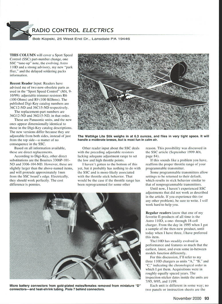
An ad caught my eye, and I wanted more information. I got exactly what I needed from Kirk, then I ordered a WattAge Lite Stik and more—and I'm really glad I did.
The Lite Stik comes complete with colored foam surfaces, a motor, gear drive, propeller, and several formed plastic fittings and parts to make assembly easier—all for less than $40. I added the new MPI single-conversion microreceiver, a Pixie electronic speed control, two FMA S-60 servos, and a six-cell 110 mAh pack.
All-up weight is 6.3 ounces, and the model flies great. I was so pleased, I bought another—sort of a backup.
The Lite Stik goes together easily with the supplied instructions. This sort of "Almost Ready to Fly kit" even includes glue. However, I have a few things you might like to try.
- Slightly taper the aft end of the fuselage stick; the model tends to be tailheavy.
- Bend the tail skid wire, and bind it to the fuselage stick with thread.
- Sand the wing dowels as necessary; make sure they fit properly into the plastic holders before you glue them to the wing.
- Make sure the motor mount fits tightly on the fuselage stick, or it can pull off.
Finally, enjoy. I'll have more on the Lite Stik later.
Soldering motor packs — delayed continuation
The July and September 2000 columns kicked off a discussion about soldering cells into motor packs, with promises of more details to follow.
For those wondering whether it is, it's still coming!
I purposely delayed this topic's continuance when I learned of a new, related product that sounded good, and was due out "any day now." The product may have strong reader appeal, and I want to check it out. Please stay with me.
Please enclose an SASE with any correspondence for which you'd like a reply. I do respond to all incoming reader mail, and I do not use E-mail for this purpose.
—MA
Transcribed from original scans by AI. Minor OCR errors may remain.

