
RC Electrics
Bob Kopski, 25 West End Dr., Lansdale PA 19446
THIS COLUMN will discuss a nifty screwdriver discovery for all aeromodelers, more reader input about the Universal Slow Charger, reader queries about motor "sizes," how to make needle voltage probes, and update information on the January 2001 column regarding homemade panel labels.
Late-arriving info: The Lehigh Valley RC Society (LVRCS) of Pennsylvania has announced its annual Electric Fun Fly for June 9 and 10. This is a great meet, and I've never missed one.
You can get more info from Mike Stewart, 107 Taft Terr., Washington NJ 07882; Tel.: (908) 689-6981.
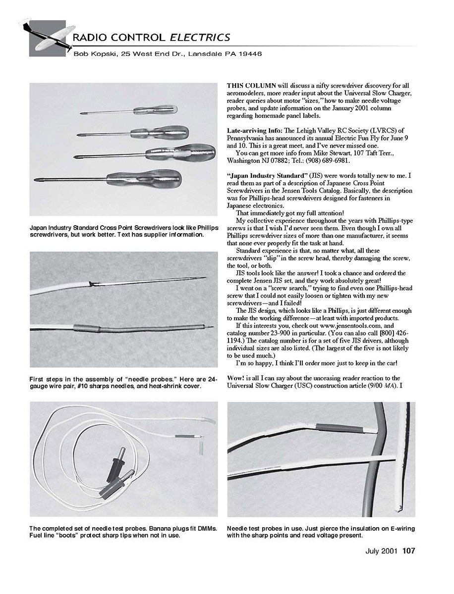
JIS (Japanese Industry Standard) screwdrivers
"Japan Industry Standard" (JIS) were words totally new to me. I read them as part of a description of Japanese Cross Point Screwdrivers in the Jensen Tools Catalog. Basically, the description was for Phillips-head screwdrivers designed for fasteners in Japanese electronics.
That immediately got my full attention!
My collective experience throughout the years with Phillips-type screws is that I wish I'd never seen them. Even though I own all Phillips screwdriver sizes of more than one manufacturer, it seems that none ever properly fit the task at hand.
Standard experience is that, no matter what, all these screwdrivers "slip" in the screw head, thereby damaging the screw, the tool, or both.
JIS tools look like the answer! I took a chance and ordered the complete Jensen JIS set, and they work absolutely great!
I went on a "screw search," trying to find even one Phillips-head screw that I could not easily loosen or tighten with my new screwdrivers—and I failed!
The JIS design, which looks like a Phillips, is just different enough to make the working difference—at least with imported products.
If this interests you, check out www.jensentools.com, and catalog number 23-900 in particular. (You can also call [800] 426-1194.) The catalog number is for a set of five JIS drivers, although individual sizes are also listed. (The largest of the five is not likely to be used much.)
I'm so happy, I think I'll order more just to keep in the car!
Universal Slow Charger (USC) — reader feedback
Wow! is all I can say about the unceasing reader reaction to the Universal Slow Charger (USC) construction article (9/00 MA). I don't understand why some manufacturer has not caught on to this apparent need within modeldom.
Some interesting points have come from these reader inputs, and I want to share them.
More than one reader had some kind of early construction problem that caused the USC internal fuse to blow, and several attempted to “fix” the problem by substituting a higher-rated fuse. This is not the thing to do!
For those among you of sufficient “maturity,” this is roughly equivalent to putting “a penny behind the fuse” in house wiring of old! Never “just put in a bigger fuse”! The specified fuse is part of the overall USC electrical design—not a random or accidental choice. If it blows, something is wrong. Find the problem that is causing this protective device to do its job, and fix it.
If you need help, here I am! Everyone who inquired of me with this (or any) USC problem got fixed up, and is happily charging away—as far as I know.
Some had what turned out to be component polarity errors. Some had electrolytic capacitors and others had diodes in backward.
The drawings do show the aspects correctly, so when all else fails, review the instructions! Better yet, preempt these troubles by following the instructions from the start.
One reader missed the article reference to DMM; i.e., the expressed use of a Digital Multi Meter for USC checkout. He tried to apply a classic analog (moving needle) meter instead, and was not getting all the right results.
It was a pleasure working with this modeler, and we finally did get his USC up and running—meter notwithstanding. Here was another instruction oversight—with a happy outcome, but a whole lot more work!
Incidental to all the above, the USC article has demonstrated that there is a steady stream of “new” MA readers. Since there has been ongoing discussion about the USC in this column for several months, some newer readers have learned what they missed previously.
You can request article copies from AMA Headquarters—for the USC or anything else.
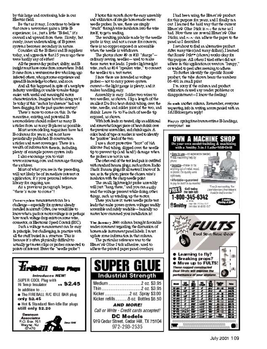
Alternative adhesive for home-printed instrument-panel overlays; most glue sticks don't work. See text, January column.
Motor "sizes"
Motor “sizes”—a “topical plague” from the earliest days of Electric—continues as such to this very day.
It's common for new E-aeromodelers to quickly learn what experience-charged fliers know: you likely can't tell much about a motor by its label.
This matter has warranted more column space in the 18-plus years of “RC Electrics” than any other topic.
Early on I argued, and even begged, for “everyone” to come together and formulate a mutually agreeable method of describing and designating motors for aeromodeling use—with no off-the-shelf.
Looking back, and imagining the future, now I feel that this is a lost cause. Given the large increase in manufacturers/suppliers in the E-field, the long-established and mostly meaningless motor nomenclature, the historically strong personalities that prevail in this area, and the recent explosion in micro-aircraft and the associated myriad of tiny motors, I see no likelihood of a sensible standard emerging—ever.
Although some may be glad that my diatribe on this subject is waning, other newer E-modelers will be puzzled, and even stymied, by this large and continuing hole in our Electric field.
Be that as it may, I continue to believe that once a newcomer gains a little E-experience; i.e., just a little "E-feel," it's onward and upward from there. Slowly, but surely, inner understanding of E-power systems becomes secondary in nature.
Consider all the E fliers and E suppliers today, and appreciate that 25 years ago there were hardly any of either!
All the present-day product, ability, and E-interest must have come from somewhere. It did. It came from a worrisome few who got in, infected others, who got some experience and spread E knowledge to others, and so on.
And all this happened in spite of the near-psyche industry unwilling or unable to make things easier with useful and meaningful motor characterization. Imagine how far along we'd be today if this "motor-by-nomen" had not been nagging for the past quarter-century!
There's more to come on this. In the meantime, existing and potential E-aeromodelers should collect as many E-articles from as many E places as possible.
Model- and motoring magazines have had E-columns for years, and most have periodically published E construction articles and motor coverage. There is a wealth of information therein, including plenty of example power-system info.
I also encourage you to visit www.e-zonemag.com and rummage through the archives.
Most of what you see in the preceding will not likely be of immediate interest or application; it's your personal reference library for ongoing use.
As a previous paragraph began, "there's more to come"!
Needle voltage probes (homemade meter probes)
Power-system measurements can be a challenge—especially for systems already installed in aircraft. Often, one would like to know what a pack or motor/vreg is doing: how much voltage drop exists on some wire, connector, or Electronic Speed Control (ESC).
Such voltage measurement can be easy in principle, but challenging in practice with all the stuff buried in a structure. This is because it's often physically difficult to actually get meter clips or probes connected to points of interest. Enter the "needle probe"!
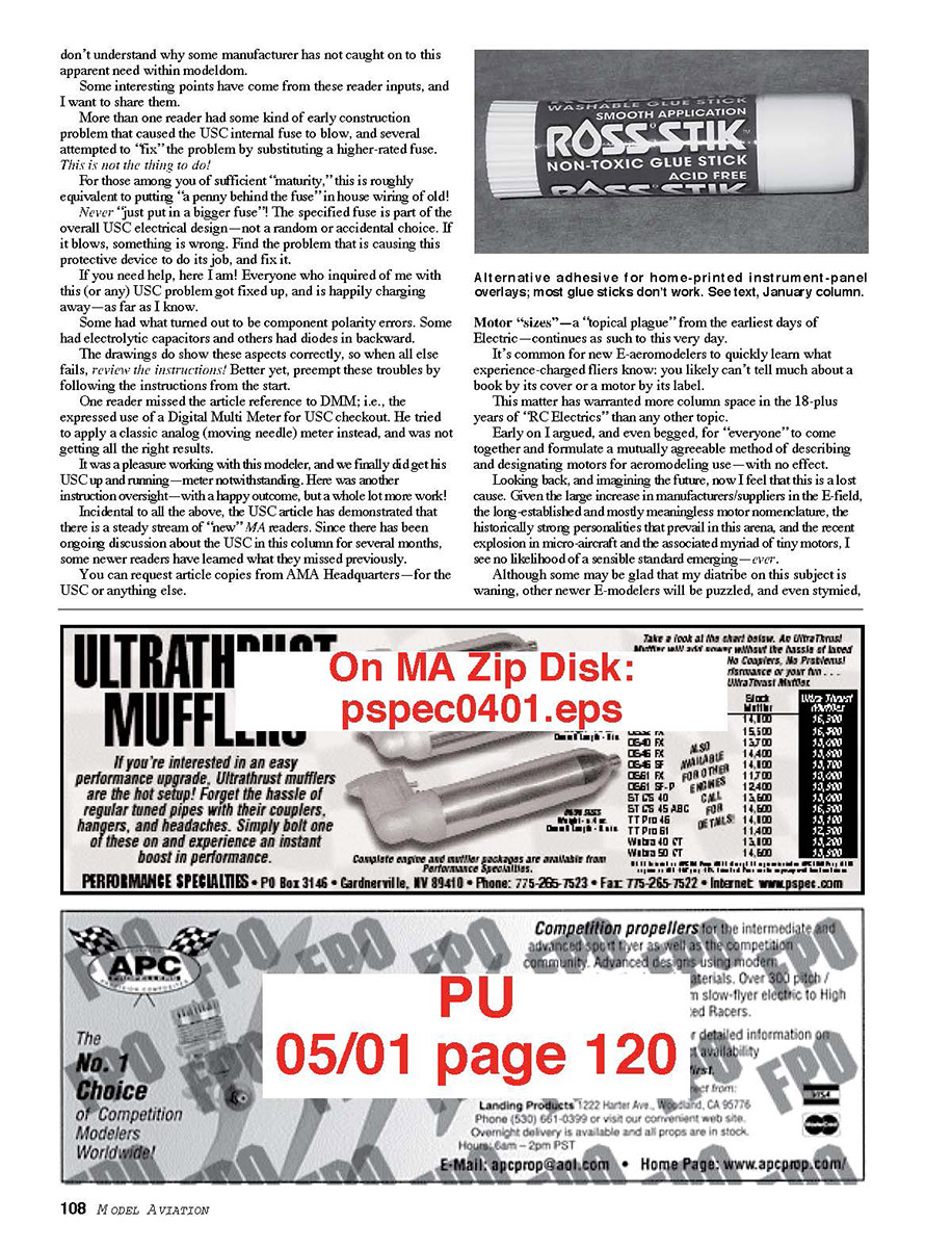
Photos this month show the easy assembly and utilization of simple homemade meter needle probes. In use, these are simply "stuck" through wire insulation into the wire itself, to get a reading.
The resulting pinhole made by the needle probe is tiny, and not a cause for concern; there is no exposed copper to cause a short when the needle is withdrawn.
The photos show #0 or #10 "sharps" ordinary sewing needles—used to make these meter test leads. I prefer lightweight wire, such as #24 "speaker wire," to connect the needles to a test meter.
Since these are intended as voltage probes—not to carry power-system current—the light gauge is plenty, and it makes handling easy.
Assembly is easy:
- Solder two wires to two needles, as shown.
- Slip a length of the smallest Du-Bro heat-shrink tubing over the wire, needle, and solder joint of the two, and shrink. Leave 1/4- to 1/2-inch of needle tip exposed.
- With both leads so treated, slip an additional and somewhat longer piece of heat-shrink over the previous assemblies, and shrink again.
- Use a color band of tape or a marker to identify the "positive" lead of the pair.
- Optionally use a short protective "boot" of 1/4-inch silicone fuel tubing slipped over the needle tip to prevent tip (and hand!) damage when the probes are not in use.
- Outfit the other end of the test lead pair with standard banana plugs (Radio Shack or similar). Banana plugs fit all meters I know of.
In use, pierce the chosen wire's insulation with the sharp needle point. The small, lightweight probe assembly will just "hang there," and you can easily read the voltage present while doing other things, such as winding up the motor.
These you have: meter needle probe test leads that make power-system voltages readily accessible and safely readable—basically no matter how crammed your installation is!
Panel label adhesive update
The January 2001 column brought a favorable reader comment regarding the discussion of homemade instrument-panel labels. I must update some information in that column.
The particular reference was to the Elmer's® Glue Stick adhesive, used to adhere the printed paper panel overlays.
I had been using the Elmer's® product for this purpose for years, and I finally ran out. I learned the hard way that the current Elmer's® Glue Stick is not the same as I had. Now there are several Elmer's® Glue Sticks, and some can adhere the paper to the panel as I described.
I set about to find an alternative product. After many tries (and many dollars), I learned that Reece's® Stik™ works okay for this purpose. All others I tried either did not adhere in this application or were "lumpy," or tended to peel after seeming to adhere.
To further identify the specific Reece's® product the tube shown bears the numbers 06-491 in small print.
I'm sorry if the column and product utilization caused any reader problems or disappointment—I know the feeling!
See another column. Remember, everyone requesting info in writing, accompanied with an SASE, does get a reply!
Happy springtime/summertime E-landings, everyone! ao
Transcribed from original scans by AI. Minor OCR errors may remain.

