

RC Electrics
Bob Kopski, 25 West End Dr., Lansdale PA 19446
THIS COLUMN will describe a nonintrusive way to mount a timer on your transmitter, explain some electrical and charging topics, and follow up on the battery-cooling topic from last month.
Electric fliers, more so than other modelers, are likely to have some kind of timer running while they are flying. Some like using a stopwatch to clock elapsed time, while others prefer a countdown timer with a "beep."
Whatever one's preference, it's generally preferred to have such a timer in view and within easy reach. This is desired so that a timer can be started and stopped easily, and is readily visible during a flight.
From what I've seen on the local flightline, and especially at a large impound, such as at last year's NEAT (Northeast Electric Aircraft Technology) meet, it's clear that many modelers struggle with ways to physically mount a timer on a transmitter.
Most don't want to modify the transmitter case in any way, and that's understandable.
I've seen varied approaches, including clamps, tie-wraps, Velcro™, rubber bands, tape, and combinations of all these, but all seem to fall short of good functionality.
However, one very functional approach is easy, inexpensive, and will not impair the transmitter case.
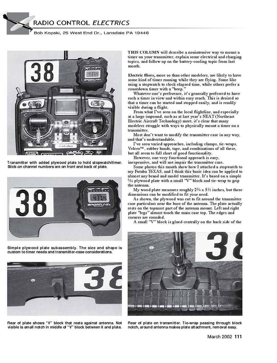
Some photos this month show how I attached a stopwatch to my Futaba T6XAS, and I think this basic idea can be applied to almost any brand and model transmitter. It's based on a simple 3/32 plywood plate with a small "V" block and tie-wrap to grip the antenna.
My wood plate measures roughly 2¾ x 5½ inches, but these dimensions can be modified to fit your transmitter.
As shown, the plywood was cut to fit around the transmitter case particulars near the base of the antenna. The plate actually rests on the topmost part of the antenna mount. Left and right plate "legs" almost touch the main case top. The edges and corners are rounded.
A small "V" block is glued centrally on the back side of the plate near the bottom edge. The exact dimensions of this small block are not critical, but mine is approximately one-inch long.
The block thickness is such that when the "V" is against the antenna, the back of the board just touches the box top handle. The idea is to stop the mounted plate from rotating on the top of the case.
You may have to add some personalization to accomplish the same effect for your transmitter case. I sprayed the assembled woodwork with gray Krylon®; it almost matches the transmitter case.
The "V" block has a small, central clearance notch cut in the surface that glues to the plate. This allows a small tie-wrap to pass between the plate and the "V" block, and to eventually close around the antenna.
My stopwatch is mounted to the plate front with two small sheet-metal screws, but double-stick foam tape or a hook and loop fastener will do nicely too. It's located so that it's easy to tap the buttons for start/stop timer operations.
The extra space on my plate permits easy placement of stick-on channel numbers on the front and back. This is somewhat a bonus; the numbers don't flop around loosely on the antenna and are generally easy to see.
I've had this timer-mount in use for two years, and I have found no reason to modify it in any way. It worked out very well from the "first shot."
There are no infringements on the transmitter case, and it's easy to remove, if need be, by cutting the tie-wrap. I had to do this to get the photos herein.
You should be able to adapt this approach to your needs and have your timer visible and in easy reach at all times!
New E-aeromodelers often share one common area of confusion. It's the area involving various such as "voltage," "current," "constant current," and so on.
It happens that "voltage" — a common electrical term — is usually the most familiar and "comfortable" term for modelers. People seem at ease with it, even if they don't fully appreciate the depth of meaning.
Household outlets provide roughly 120 volts AC for appliances. Not only that, but this voltage is rather "constant," so it's nominally the same whether you plug in a four-watt night-light or a 1,000-watt clothes iron.
The same idea holds for other voltage sources, such as the auto battery, a flashlight battery, and transmitter, receiver, and motor packs. "Voltage source" literally means a source of voltage that is unaffected by any load.
But practically speaking, no real source of voltage is perfect; all have at least some small internal resistance. This means that a load can actually affect the voltage value to some degree.
Thus, if one looks closely, any of the common "voltage sources" do actually drop some in terminal voltage as a function of how "heavy" the connected load is; i.e., how much current it takes.
If you measured your household outlet voltage with a night-light plugged in, and then with a clothes iron connected, you'd likely find a small voltage change — lower with the iron, of course.
Now enter the "current source." Here's where many people have pictorialization problems, probably because there are so many common or familiar current sources around the house.
But E-aeromodelers use them all the time, given that many chargers are "constant-current" chargers. So what does this mean?
A constant current source (e.g., many chargers) supplies the same current no matter how much voltage the load "uses up."
Think of a current source as the "dual" of the more familiar "voltage source." Thus a constant-current charger supplies the same current no matter the number of cells connected, up to the limits of its design.
It doesn't matter if it is a fast field charger (such as the Astro 110D) or a slow charger (such as the Universal Slow Charger, 9/00 MA). If a charger is "constant current," be it one cell or the specified maximum number, the charge current is nominally the same.
As are all the common voltage sources that are slightly imperfect, all physical current sources (like chargers) are somewhat imperfect. If you measure carefully, you'll no doubt see a slight change in current value as you go from minimum to maximum cell count.
This brings me to some in-between sources — those that are neither voltage nor current sources, but that deliver an output that very much depends on the load itself.
The familiar "wall-rat" charger for radio systems fall into this category. The most common of these are 50 mA slow ("overnight") chargers because most receiver and transmitter batteries are 500 mA packs.
But these chargers are neither voltage sources nor current chargers in the strictest sense. The charging current is only the specified value (such as 50 mA) for a specific number of cells; four and eight are the usual number for radio stuff.
Thus these chargers are designed with sufficient internal voltage and purposeful internal resistance so that the intended charge current flows with only the specified pack in place. Change the intended cell count, and the effective charging current changes.
So without measuring, one cannot know what current is flowing for packs with other cell counts, such as the five, six, or seven cells in the popular park-flyer packs.
I know many people are disappointed to get this news, but that's the way it is.
Because of the boom in "indoor flyers," "park flyers," and the like in recent years, many modelers are faced with slow-charging a wide variety of "small" packs. These include Ni-Cd and NiMH chemistries, with cell counts of one to 10, and with cell capacities ranging from approximately 50 mAh to 1,000 mAh.
In addition, many modelers typically have several packs per airplane. I, and other modelers, often want to do slow-charging (overnight charging) in the car—great at weekend meets. It's a new, varied need that did not previously exist.
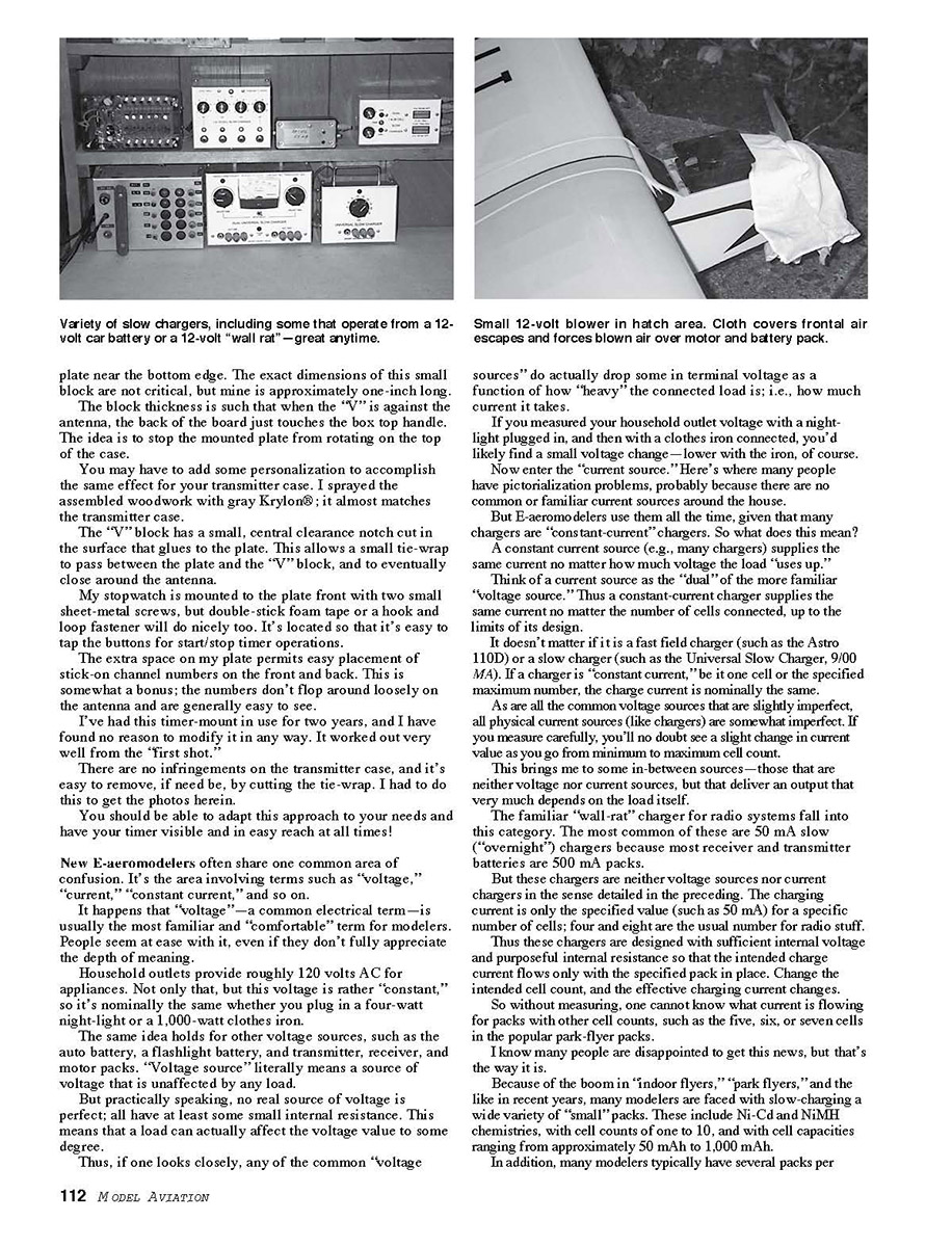
One photo shows several home-brew slow chargers I've concocted through the years. One dates to the 1960s and is still in use! Others are quite new, and some are designed to operate from 12-volts input — from a "wall wart" or from the car battery.
All my newer slow chargers are truly "constant current"; I don't have to consider cell count up to the design limit. Some have a range of fixed-value current outputs, and some have adjustable currents.
Don't confuse "constant current" with "adjustable current"; the latter allows you to choose the current value, and the former assures that it stays where you put it.
One charger shown that I like very much is that in the upper right corner. It runs from 12-volts input for in-home or in-car use and has two independent outputs.
Each output is adjustable from 0 to 100 mA and is monitored with a bar-graph display. Each output can charge from one to 28 cells.
All this means I can charge a single 20 mAh cell at 25 mA on one output and a bunch of individual 1,000 mAh packs connected in series up to 28 cells total at 100 mA, or any combination in between.
Each output has multiple output connectors, so I can plug in pack after pack after pack. And it's very efficient; there's very little lost power and heat, so it's easy on the car battery.
This charger uses all readily available parts and supplies, but it is a serious, sizable project to build. If there's enough interest, perhaps I can offer a feature article. (Please don't ask for drawings in advance; I don't have any that are adequate for sharing—period!)
Or perhaps you'd like to share your specific needs on-line. Let me know what you'd like to see, and if enough readers have much the same descriptions, I may undertake a design for the majority interest.
I described Big Bio last month. It is a high-versatility battery cooler that is based on a standard 12-volt fan available from many electronic-parts suppliers.
One photo shows a smaller version of the fan I described last month doing some cooling in a different way.
Several people on my flightline use a variety of sizes of these small fans to cool stuff in the airplane. The photo shows one resting in place of a normal hatch cover. A small cloth covers some front openings to keep cooling air flowing over the motor and back through the motor pack.
Like last month's discussion, this blower operates from 12 volts and draws very little current. In all, there are roughly six standard sizes of these little fans, and you can probably find one well-suited to your custom needs.
Most electronic suppliers have these, but you can also check out jameco.com and hosfelt.com for your needs.
So ends another monthly column. Everyone enclosing a S.A.S.E. with letters seeking a reply does get one, so a word to the wise...!
Meanwhile, have a great "electric-flyin'" late winter and early spring, with many safe and happy flying!
Transcribed from original scans by AI. Minor OCR errors may remain.

