
RC Electrics
THIS COLUMN WILL continue the battery-cooler discussion of the last two columns, share some little-known info about a popular charger, and share several reader inputs.
The February column described Big Blo—a fan assembly I use to cool packs removed from airplanes between flights. The March column showed one way to do this cooling job for packs remaining in airplanes.
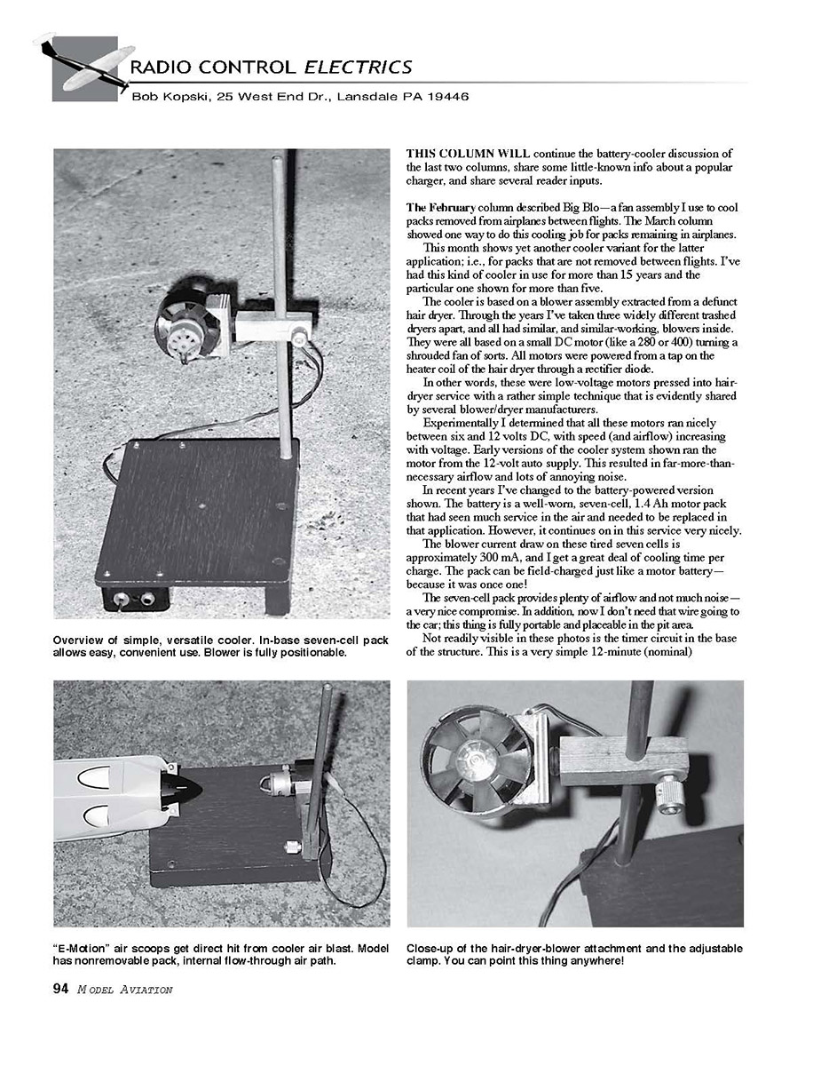
This month shows yet another cooler variant for the latter application; i.e., for packs that are not removed between flights. I've had this kind of cooler in use for more than 15 years and the particular one shown for more than five.
The cooler is based on a blower assembly extracted from a defunct hair dryer. Through the years I've taken three widely different trashed dryers apart, and all had similar, and similar-working, blowers inside. They were all based on a small DC motor (like a 280 or 400) turning a shrouded fan of sorts. All motors were powered from a tap on the heater coil of the hair dryer through a rectifier diode.
In other words, these were low-voltage motors pressed into hair-dryer service with a rather simple technique that is evidently shared by several blower/dryer manufacturers.
Experimentally I determined that all these motors ran nicely between six and 12 volts DC, with speed (and airflow) increasing with voltage. Early versions of the cooler system shown ran the motor from the 12-volt auto supply. This resulted in far-more-than-necessary airflow and lots of annoying noise.
In recent years I've changed to the battery-powered version shown. The battery is a well-worn, seven-cell, 1.4 Ah motor pack that had seen much service in the air and needed to be replaced in that application. However, it continues on in this service very nicely.
The blower current draw on these tired seven cells is approximately 300 mA, and I get a great deal of cooling time per charge. The pack can be field-charged just like a motor battery—because it is once one!
The seven-cell pack provides plenty of airflow and not much noise—a very nice compromise. In addition, now I don't need that wire going to the car; this thing is fully portable and placeable in the pit area.
Not readily visible in these photos is the timer circuit in the base of the structure. This is a very simple 12-minute (nominal).
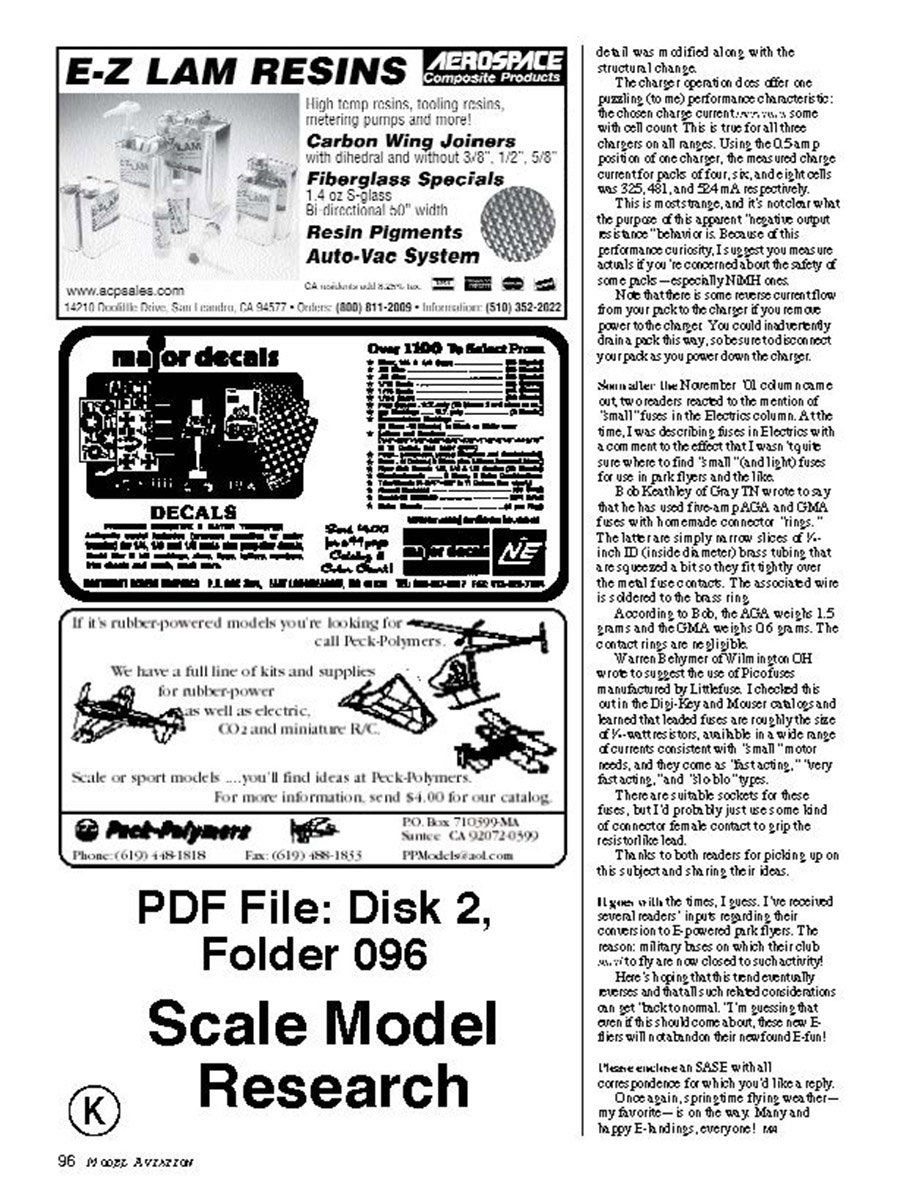
As for this cooler's versatility, the blower-fan assembly is fully positionable. The vertical travel on the dowel rod extending from the base is roughly 10 inches, but you can change it as you wish. As you can see in the photos, this provides good "reach" for a variety of applications. In addition to the up-down positioning, the clamp assembly can rotate 360° around the dowel.
The clamp assembly is a ¾-inch-square, 2½-inch-long piece of wood that is bored crosswise then saw-slitted to ride on the dowel. Tightening the thumbscrew squeezes the saw slit closed and snugs the clamp in place along the dowel at the chosen height.
The blower shroud is double-sticky-foam taped onto a wood "V" block, and the base of this block is held to the end of the ¾-inch-square clamp arm with a not-quite-tight wood screw.
Between the two is a slightly squeezed rubber grommet which serves as a friction device. The motor/"V"-block subassembly can be rotated 360° on the screw then will stay put with the friction afforded by the compressed grommet.
The base of this cooler measures 6 x 8 inches, but this detail is not critical. The base material is ¼ plywood supported on two "side rails." One "rail" is really a cut-down RadioShack® plastic box that supports the seven-cell pack, switch, charge jack, and timer circuit. The other is a wood rail cut to be as deep as the battery-box assembly.
The total base height is 1½ inches. Some stick-on rubber feet keep the cooler from traveling along the floor of my minivan.
This simple and versatile cooler is low-cost, fully portable, and fully positionable to direct cooling air at whatever the need. This unit finds use nearly every time I go to the field!
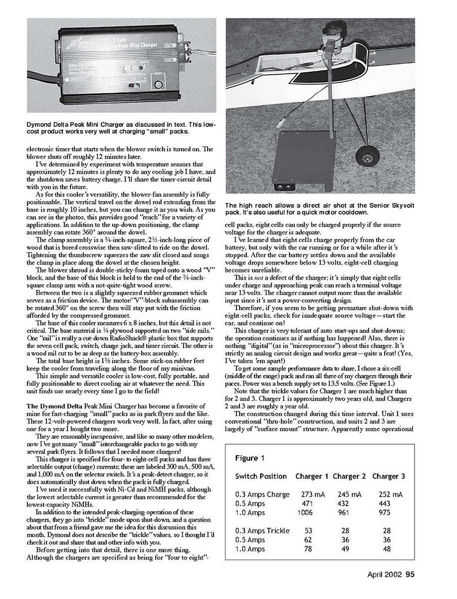
The Dymond Delta Peak Mini Charger has become a favorite of mine for fast-charging "small" packs as in park flyers and the like. These 12-volt-powered chargers work very well. In fact, after using one for a year I bought two more.
They are reasonably inexpensive, and like so many other modelers, now I’ve got many "small" interchangeable packs to go with my several park flyers. It follows that I needed more chargers!
This charger is specified for four- to eight-cell packs and has three selectable output (charge) currents; these are labeled 300 mA, 500 mA, and 1,000 mA on the selector switch. It is a peak-detect charger, so it does automatically shut down when the pack is fully charged.
I’ve used it successfully with Ni-Cd and NiMH packs, although the lowest selectable current is greater than recommended for the lowest-capacity NiMHs.
In addition to the intended peak-charging operation of these chargers, they go into "trickle" mode upon shut-down, and a question about that from a friend gave me the idea for this discussion this month. Dymond does not describe the "trickle" values, so I thought I’d check it out and share that and other info with you.
Before getting into that detail, there is one more thing.
Although the chargers are specified as being for "four to eight" cell packs, eight cells can only be charged properly if the source voltage for the charger is adequate.
I’ve learned that eight cells charge properly from the car battery, but only with the car running or for a while after it’s stopped. After the car battery settles down and the available voltage drops somewhere below 13 volts, eight-cell charging becomes unreliable.
This is not a defect of the charger; it’s simply that eight cells under charge and approaching peak can reach a terminal voltage near 13 volts. The charger cannot output more than the available input since it’s not a power-converting design.
Therefore, if you seem to be getting premature shut-down with eight-cell packs, check for inadequate source voltage—start the car, and continue on!
This charger is very tolerant of auto start-ups and shut-downs; the operation continues as if nothing has happened! Also, there is nothing "digital" (as in "microprocessor") about this charger. It’s strictly an analog circuit design and works great—quite a feat! (Yes, I’ve taken ’em apart!)
To get some sample performance data to share, I chose a six-cell (middle of the range) pack and ran all three of my chargers through their paces. Power was a bench supply set to 13.5 volts. (See Figure 1.)
Note that the trickle values for Charger 1 are much higher than for 2 and 3. Charger 1 is approximately two years old, and Chargers 2 and 3 are roughly a year old.
The construction changed during this time interval. Unit 1 uses conventional "thru-hole" construction, and units 2 and 3 are largely of "surface mount" structure. Apparently some operational
Figure 1
Switch Position Charger 1 Charger 2 Charger 3 0.3 Amps Charge 273 mA 245 mA 252 mA 0.5 Amps 471 mA 432 mA 443 mA 1.0 Amps 1006 mA 961 mA 975 mA
0.3 Amps Trickle 53 mA 28 mA 28 mA 0.5 Amps Trickle 62 mA 36 mA 36 mA 1.0 Amps Trickle 78 mA 49 mA 48 mA
detail was modified along with the structural change.
The charger operation does offer one puzzling (to me) performance characteristic: the chosen charge current varies a bit with cell count. This is true for all three chargers on all ranges. Using the 0.5 amp position on one charger, the measured charge current for packs of four, six, and eight cells was 325, 481, and 524 mA, respectively.
This is most strange, and it's not clear what the purpose of this apparent "negative output resistance" behavior is. Because of this performance curiosity, I suggest you measure actuals if you're concerned about the safety of some packs—especially NiMH ones.
Note that there is some reverse current flow from your pack to the charger if you remove power to the charger. You could inadvertently drain a pack this way, so be sure to disconnect your pack as you power down the charger.
Some earlier columns (the November '01 column) came out, two readers reacted to the mention of "small" fuses in the Electrics column. At the time, I was describing fuses in Electrics with a comment to the effect that I wasn't quite sure where to find "small" (and light) fuses for use in park flyers and the like.
Bob Keathley of Cary TN wrote to say that he has used five-amp AGA and GMA fuses with homemade connector "rings." The latter are simply narrow slices of 1/16-inch ID (inside diameter) brass tubing that are squeezed a bit so they fit tightly over the metal fuse contacts. The associated wire is soldered to the brass ring.
According to Bob, the AGA weighs 1.5 grams and the GMA weighs 0.6 grams. The contact rings are negligible.
Warren Behymier of Wilmington OH wrote to suggest the use of Pico fuses manufactured by Littelfuse. I checked this out in the Digi-Key and Mouser catalogs and learned that leaded fuses are roughly the size of 1/4-watt resistors, available in a wide range of currents consistent with "small" motor needs, and they come as "fast-acting," "very fast acting," and "slower" types.
There are suitable sockets for these fuses, but I'd probably just use some kind of connector (female contact) to grip the resistor/fuse lead.
Thanks to both readers for picking up on this subject and sharing their ideas.
It goes with the times, I guess. I've received several readers' inputs regarding their conversions to E-powered park flyers. The reason many bases on which their clubs previously fly are now closed to such activity? Here's hoping that this renewed community interest and some of the technical considerations can get back to normal. I'm presuming that even if this should come about, those new E-fliers will not abandon their newfound fun!
I have enclosed an SASE with all correspondence for which you'd like a reply.
Once again, springtime flying weather—my favorite—is on the way. Many and happy E-bindings, everyone!
Transcribed from original scans by AI. Minor OCR errors may remain.

