

RC Electrics
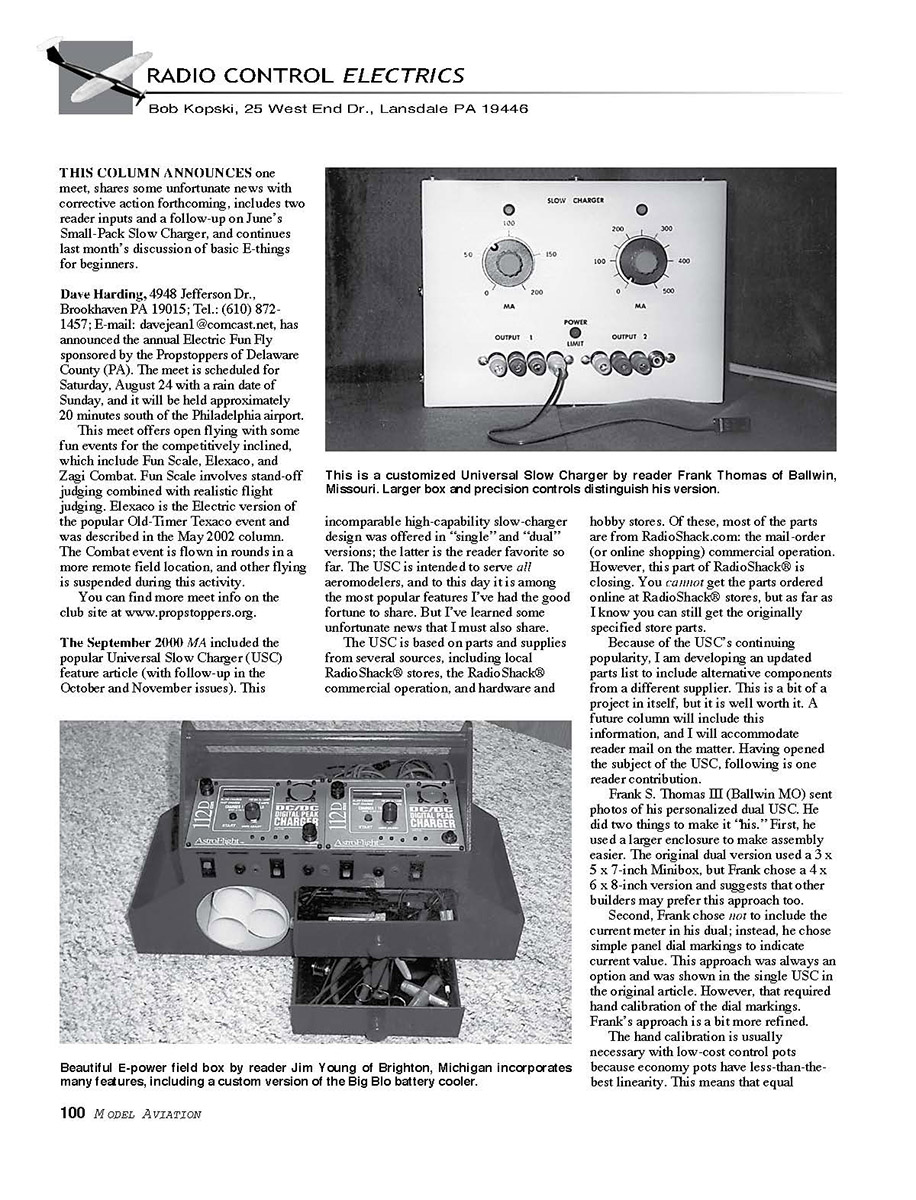
Rotational movements do not necessarily strike off equal amounts of resistance, hence charge current. As a result, incremental dial markings can be unequally spaced and would have to be measured.
Frank substituted more costly Bourns 300 electrical degree precision pots. He did not supply part numbers. However, a glance through most electronics catalogs will present many such choices. But be prepared to spend several dollars each!
So why do this? Precision pots, with more linear control response, allow one to remark accurate dial indications. Frank put markings on his painted panel using a simple compass and protractor—no custom calibration required. He tells me that this has worked out very well.
In addition, Frank set up his dual to have two current ranges and chose values of 0–200 mA and 0–500 mA. The USC article describes range options. Nice job, Frank!
Jim Young (Brighton MI) sent info about how he adapted the Big Blo battery-cooler idea (in the February 2002 column). His great-looking, custom E-field box includes two Astro 11ZD chargers, room for two transmitters, space for loose packs, two tool drawers, a five-foot cord to connect to a separate field battery, and a built-in version of Big Blo. You can’t see the brilliant red color of his creation—surely an eye-catcher on any flightline!
Jim tells me that the box is constructed mostly from 1/4 and 1/8 aircraft plywood, and that he’s thinking of sharing his CAD (computer-aided design) drawings and design details in a magazine article. I don’t know where this pursuit stands at the moment, but I hope he is able to follow through on it.
The June issue included a feature article entitled “Small-Pack Slow Charger” (SPSC), which should find much favor with many flyers. The unit works well for NiCd cells with capacities up to about 500 mAh. However, the SPSC required a separate field battery and its single, fixed charge rate limited its usefulness for some applications.
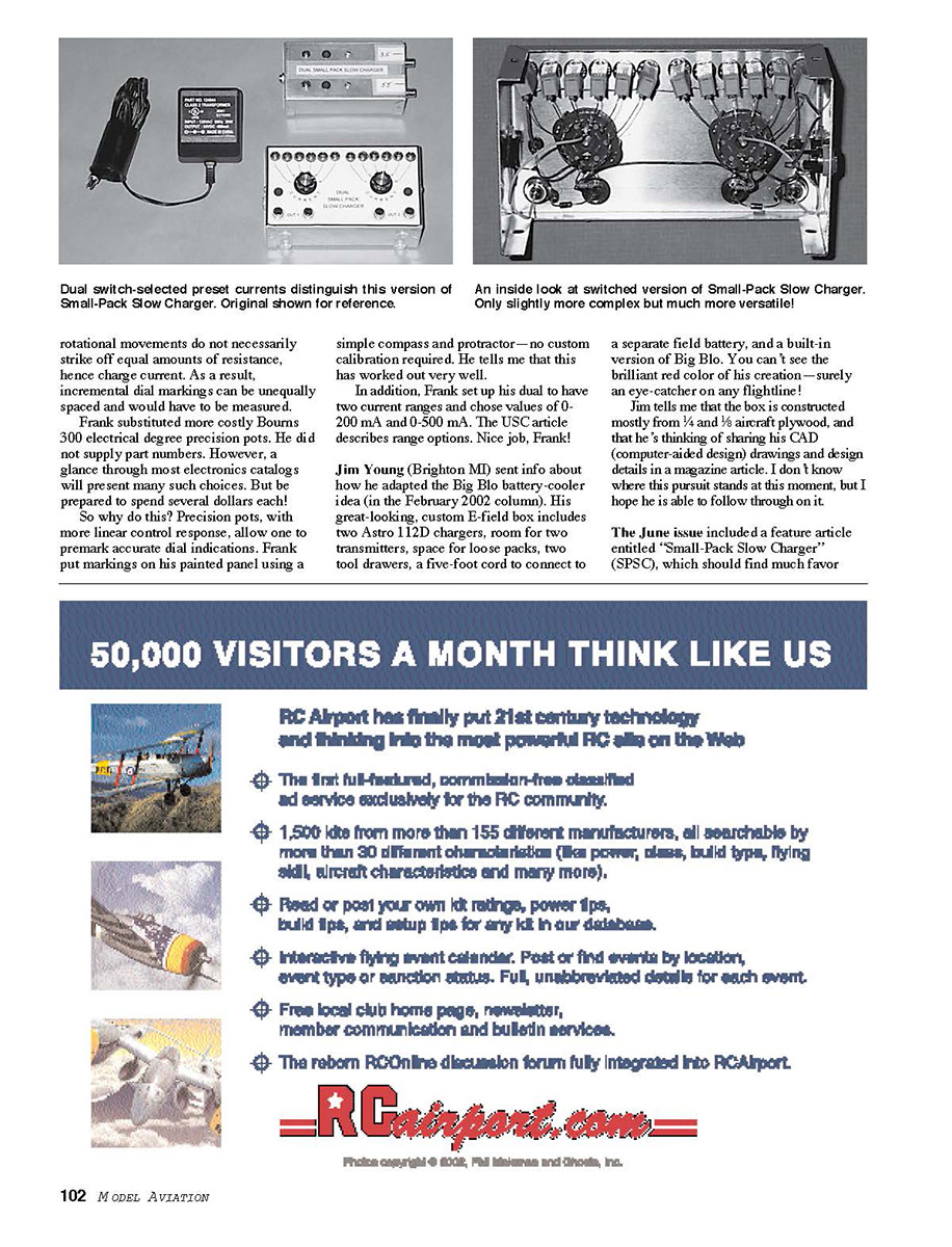
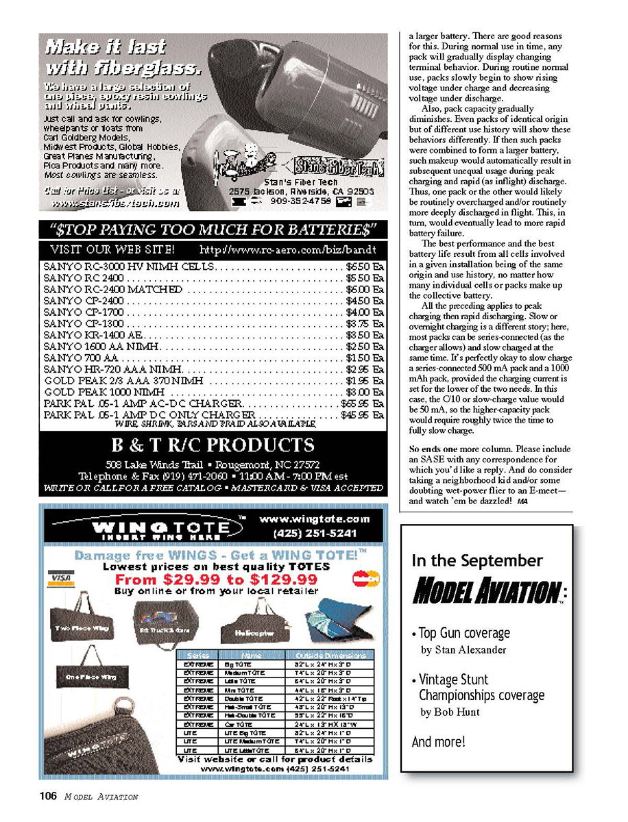
Based on suggestions from readers, Frank later developed a switched version of the SPSC that provides multiple preset charge currents. This version uses a small rotary switch to select among several resistors, each setting a different current limit. The inside layout is shown above. In practice, the switched unit offers greater flexibility without significantly increasing complexity.
Also, several readers described their homemade chargers and power supplies. Among them, Ed Smith of Columbus, OH, built a compact, high-current supply using a salvaged computer power transformer. He added a simple current-limiting circuit and a large heatsink to produce reliable charge currents for larger packs.
If you’d like to send details of your own projects, include clear photos and a short schematic or wiring diagram. I may feature selected projects in future columns.
Trimmer pots for each output. Each of the two charge-current outputs of this version can deliver any of six switch-selected preset current values. One pole of each switch selects the (Ra + Rb) combination, while the other pole selects the associated R1 value. (See original text.)
This version of the SPSC also includes two series-wired phono connectors for each output current. This allows easy connection of two packs per output. If only one is used, the unused connector is shorted with a mating plug. You can use as many such connectors as you want, but multiple connectors must be insulated from the metal box.
Clearly, this switched-current SPSC makes it easier to accommodate a wider variety of pack capacities — something common among park flyers. It also illustrates how the basic SPSC can easily be personalized to better meet one's needs and preferences. If you've got some custom idea of your own but aren't comfortable going about it, please write and I'll be happy to discuss your thoughts.
Last month's column included discussion especially for E-beginners, and this one will follow on in theme. This format will likely continue for some time into the future. I've decided to do this because of the contemporary, larger-than-ever influx of new E-aeromodellers. New E-fliers are faced with the same, often simple questions that more experienced modelers often forget once having had themselves. So although this theme will likely bore some, do remember that you too were once an E-beginner!
Last month's column described how cells are series-connected to make up packs and batteries. It also pointed out that, like cells, individual packs may be connected in series. But no matter the exact make-up of a battery, it is common for E-aeromodellers to speak simply in terms of total cell count.
The choice of using packs to make up a larger battery is often driven by simple logistics. This is because there are some favorite ready-made pack configurations that have evolved and include commonplace six and seven cell counts, for example. Aeromodelers frequently use these as premade subassemblies or building blocks to make a larger total cell count.
Consider wanting a 14-cell battery. This could be made from 14 series-connected cells. It could also be made from two commonly available seven-cell packs connected in series.
Packs used this way do not have to be of equal cell count, and any combination of cell counts can be used. However, what does matter is that the packs be "the same" in all basic parameters. They must be the same capacity (mAh), and they should be of the same manufacturing lot, and they should have the same use history.
This means that equal-capacity (mAh) packs used in series to form a larger battery should be of identical origin and always have been used together; that is, such packs should always have been wired together and charged and discharged together—just as though the 14 cells were a single-unit battery from the start.
Conversely, one must avoid interconnecting just any old packs to make a larger battery. There are good reasons for this. During normal use in time, any pack will gradually display changing terminal behavior. During routine normal use, packs slowly begin to show rising voltage under charge and decreasing voltage under discharge.
Also, pack capacity gradually diminishes. Even packs of identical origin but of different use history will show these behaviors differently. If then such packs were combined to form a larger battery, such makeup would automatically result in subsequent unequal usage during peak charging and rapid (as inflight) discharge. Thus, one pack or the other would likely be routinely overcharged and/or routinely more deeply discharged in flight. This, in turn, would eventually lead to more rapid battery failure.
The best performance and the best battery life result from all cells involved in a given installation being of the same origin and use history, no matter how many individual cells or packs make up the collective battery.
All the preceding applies to peak charging then rapid discharging. Slow or overnight charging is a different story; here, most packs can be series-connected (as the charger allows) and slow charged at the same time. It’s perfectly okay to slow charge a series-connected 500 mA pack and a 1000 mAh pack, provided the charging current is set for the lower of the two needs. In this case, the C/10 or slow-charge value would be 50 mA, so the higher-capacity pack would require roughly twice the time to fully slow charge.
So ends one more column. Please include an SASE with any correspondence for which you’d like a reply. And do consider taking a neighborhood kid and/or some doubting wet-power flier to an E-meet—and watch ’em be dazzled! MA
Transcribed from original scans by AI. Minor OCR errors may remain.

