
RADIO CONTROL ELECTRICS
Bob Kopski, 25 West End Dr., Lansdale PA 19446
THIS COLUMN describes an upcoming meet, introduces a new publication, and follows up on some previous topics — including the SSC, timed charging, and my new slow charger.
Electric Meet, May 6–7
Two clubs teamed up to present an Electric meet May 6–7.
- The Winston-Salem (NC) Radio Control Club hosts the first day's flying at their field.
- The Riverside Aeromodelers host the second day at theirs.
The respective CD's are Randy Covington ((336) 983-9126) and Colin McKinley ((336) 924-5890). John Mountjoy is meet coordinator and can be reached at (336) 722-7609. If all goes as planned, there will be Wingo Races, AULD, recognition of design and building skills, plus other activities, with open flying for all.
Electrics of all kinds abound! Twenty-five years ago, curious modelers were struggling to get something — anything — E-powered to sustain flight; now, E-modelers easily fly anything and everything imaginable. That includes the very broad range from sub-one-ounce indoor craft through huge, highly capable machines weighing upward of 30 pounds.
Probably the newest "rage" within E-power lies at the low-power end — the indoor and calm-weather fliers including the so-called "park flyers" (Editor's note: see Bob Wilder's feature on these models in this issue).
New Publication: Radio Control Microflight
John Worth, AMA Executive Director emeritus, took a liking to the low-power, small E-aeromodels several years ago, and published a dedicated newsletter called Cloud Nine. John also set up to supply this niche area within aeromodeling.
Cloud Nine was a masterpiece newsletter and was a major influence in seeding interest in this specialty. Now the interest is so large that Air Age, the publisher of Model Airplane News, has arranged with John to take over and publish an expanded version called Radio Control Microflight ("The World of At-Home RC").
John Worth remains a contributor, with a column entitled "Cloud Nine," but that's only part of this new newsletter. I've seen the first issue and intend to subscribe. Interested modelers can get a sample issue by calling (800) 243-6685. You can also check out a free sample issue at www.microflight.com. A one-year subscription is $29.95 for 12 issues.
SSC, Motor Cutoff, and Reader Feedback
The January column presented the results of a year-long motor battery experiment. I described how one unique feature of the Sport Speed Control (MA, 9/99 and 10/99) seemed to significantly extend motor battery life and performance.
The SSC's "motor cutoff circuit" function, which prevents motor packs from going into a deep-discharge state, apparently prevented or delayed the onset of the "false-peak syndrome." I cautiously labeled this happy outcome a "breakthrough."
Shortly after the January column appeared, I received a rather strong reader testimonial. This modeler, who has two SSCs in use, told how he historically flew his Electrics "to the last drop" of charge, and how all his packs would quickly become defective. (I interpret his input to mean he did not previously associate the deep discharging with short pack life.) He then described trying two SSCs and how his battery problems are gone.
As detailed in the March 2000 column, I now know that the motor cutoff circuit does not totally prevent battery deterioration, but does appear to greatly delay it. I'm always appreciative of reader input, and I'm especially pleased with happy stories like this one.
Please consider sharing your SSC experiences with me, and thank you in advance. I say again, I think it might be prudent for ESC manufacturers to seriously pursue the equivalent of the SSC "motor cutoff" function.
Timed Charging vs. Peak Charging
The February 2000 column discussed another motor battery study — a "long term" study where results may not be obvious for a year or more. This pursuit resurrects the concept of "timed charging" from the earliest days of Electric in an attempt to more carefully compare it to today's peak-charging methodology.
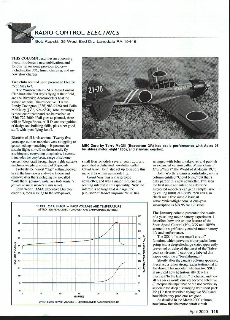
It is my observation that the last few minutes of peak charging add very little to the charge within the pack, but do add considerably to the pack temperature. A graphic depicts this situation. The pack voltage (upper curve) is very classic-looking, having the long, slow rise in battery terminal voltage with charge time. For this example, this behavior lasts up to about 21 minutes — a judgment call. At this time the battery voltage begins to rise more steeply with time and continues rapid ascent for the next three to four minutes.
The lower curve shows the case temperature of one of the cells (taken as typical) with time as the pack charges. Clearly, the temperature curve moves much like the voltage curve. Although the cell temperature curve is slightly delayed (time-lags behind the voltage motion), it is clear that as the pack voltage begins to rise sharply, the temperature does as well. This increasing temperature eventually "wins" in that, as the pack gets hotter, the rising pack temperature tends to lower pack voltage, thus "fighting" any voltage rise associated with the continuing charge current.
Putting it another way: while the continuing charge is increasing the pack voltage, the rising pack temperature is lowering the pack voltage, and eventually the latter "wins" the "voltage race," resulting in a net drop in pack voltage. This turnaround in voltage behavior is what gives the appearance of a "pack peak" at about 25 minutes in this example.
Note that it's not the peak voltage per se but rather the voltage change in direction (voltage decline) that is the cue for the charger to shut down — shown here at about 25½ minutes. Relatively speaking, by the time this shutdown occurs, pack temperature is much higher than it had been only minutes prior. For the sample graphic shown, this sudden rise is about 27°.
Based on numerous measurements I've made, most of the charge that a pack can accept is already in place at just around the beginning of the voltage and temperature rise (about 21–22 minutes for this example).
Although it is true that one can actually get a fraction of a minute more motor run from peak charging, I question the resulting "flight quality" associated with this additional charge. In particular, because the pack is noticeably hotter at the end of (peak) charge, it is that much hotter at the end of flight as well, and I think that this added temperature can sufficiently degrade flight performance more near the end of flight than the short additional flight time itself warrants.
This is very hard to quantify, hence the "I think" statement above. But whether it's really the case or not is not the reason for my pursuing the old "timed charge" idea. I'm more interested in any possible effects on pack life, and/or pack performance over life, that may result from this "kinder, gentler" pack handling.
Looking at the whole picture, I'm now pursuing motor battery pack effects resulting from the combination of timed charge (where the pack is not "overfilled") and "motor cutoff" as implicit with the SSC design. Think of this as a "double-barreled" experiment.
Large Pack Slow Charger (USL) Development
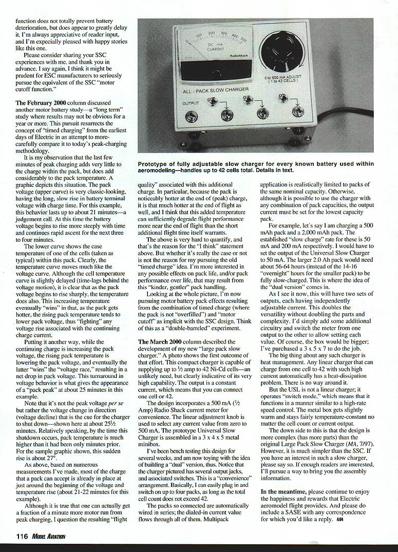
The March 2000 column described the development of my new "large pack slow charger." A photo shows the first outcome of that effort. This compact charger is capable of supplying up to 1/2 amp to 42 Ni-Cd cells — an unlikely need, but clearly indicative of its very high capability. The output is a constant current, which means that you can connect one cell or 42.
The design incorporates a 500 mA (1/2 Amp) Radio Shack current meter for convenience. The linear adjustment knob is used to select any current value from zero to 500 mA. The prototype Universal Slow Charger is assembled in a 3 x 4 x 5 metal project box.
I've been bench testing this design for several weeks, and am now toying with the idea of building a "dual" version. Notice that the charger pictured has several output jacks and associated switches. This is a "convenience" arrangement. Basically, I can easily plug in and switch on up to four packs, as long as the total cell count does not exceed 42.
The packs so connected are automatically wired in series; the dialed-in current value flows through all of them. Multipack application is realistically limited to packs of the same nominal capacity. Otherwise, although it is possible to use the charger with any combination of pack capacities, the output current must be set for the lowest capacity pack.
For example:
- If charging a 500 mAh pack and a 2,000 mAh pack together, the established "slow charge" rate for these is 50 mA and 200 mA respectively.
- You would have to set the output of the Universal Slow Charger to 50 mA.
- The larger 2.0 Ah pack would then need about 56–64 hours (instead of the 14–16 "overnight" hours for the smaller pack) to be fully slow-charged.
This is where the idea of the "dual version" comes in. As I see it now, this will have two sets of outputs, each having independently adjustable currents. This doubles the versatility without doubling the parts and complexity. I'd simply add some additional circuitry and switch the meter from one output to the other to allow setting each value. Of course, the box would be bigger; I've purchased a 3 x 5 x 7 to do the job.
The big thing about any such charger is heat management. Any linear charger that can heat from one cell to 42 with such high current automatically has a heat-dissipation problem. There is no way around it.
But the USL is not a linear charger; it operates "switch mode," which means that it functions in a manner similar to a high-rate speed control. The small box gets slightly warm and stays fairly temperature-constant no matter the cell count or current output.
The downside to this is that the design is more complex (has more parts) than the original Large Pack Slow Charger (MA, 7/97). However, it is much simpler than the SSC. If you have an interest in such a slow charger, please say so. If enough readers are interested, I'll pursue a way to bring you the assembly data.
In the meantime, please continue to enjoy the happiness and rewards that Electric model flight provides. And please do include a SASE with any correspondence for which you'd like a reply. MA
Transcribed from original scans by AI. Minor OCR errors may remain.

