
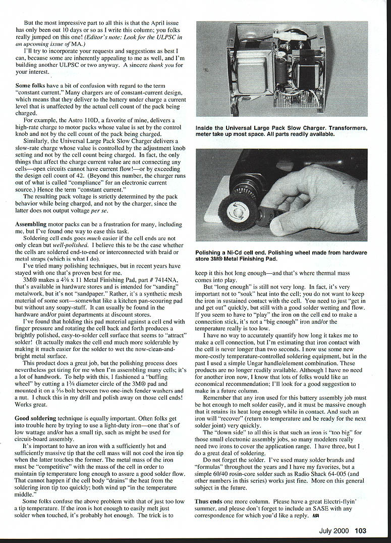
RADIO CONTROL ELECTRICS
Bob Kopski, 25 West End Dr., Lansdale PA 19446
This column will cover a meet announcement, an SSC "Assembly Aid" and related comments, some reader input, and soldering Ni-Cd cells.
Gordon Wheeler of Central New York's Voltaires Electric Club wrote to tell me of the Voltaires 15th Annual Electric Fun Fly scheduled for July 15-16. The meet will be held on the Grenadiers Flying Field in the Syracuse area. I've heard that last year's meet surprised everyone with a tremendous turnout, so I'd expect more of the same this year.
You can get all the details from:
- Gordon Wheeler, 5 Old Farms Ln., Cazenovia NY 13035; Tel.: (315) 655-9068; E-mail: [email protected]
- Garret Wikoff; Tel.: (315) 695-4271; E-mail: [email protected]
Reader comment continues on the Sport Speed Control (9-10/99 MA). A clear picture of the most-common problems is emerging.
By far, the largest trouble category is "miswires," with a subcategory of "missed wires." All this is perfectly understandable; the SSC has a lot of parts and therefore a lot of parts connections.
I certainly can understand how some parts get installed in the wrong holeboard holes, or perhaps "backward" in the case of polarized parts like diodes and some capacitors. Yet in every case I know about, when the miswire was corrected, the SSC worked properly.
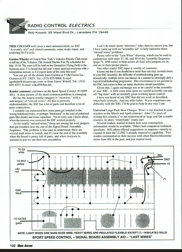
As for totally "missed wires," these are among the wire jumpers that get installed near the end of the Signal Board Assembly Sequence. This problem is also easy to understand; there are several such wires to install, and it's near the end of the assembly when the board is pretty full of parts, and when everyone is anxious to just try out their new assemblies.
I can't do much about "miswires" other than to caution you, but I have come up with an "assembly aid" to help minimize those "missed wires" problems.
Please refer to the "Last Wires" drawing, which can be used in conjunction with steps 37, 38, and 39 of the Assembly Sequence (page 71, 9/99 issue) to help assure all final wire jumpers are in, and are in their proper places.
One other reader SSC input is worthy of comment: it turns out that if you should have more than one, say several, errors in your SSC assembly, the difficulty of troubleshooting goes up dramatically; multiple errors can interact in a manner to seemingly defy a logical troubleshooting progression. This circumstance is not peculiar to the SSC, but comes to bear on many electronic circuit assemblies.
Given this, I again encourage you to be careful in the assembly of your SSC. A little extra time spent on careful assembly can pay off "big time" with an instantly great-working speed control.
I have not heard of any SSC that did not work as described, when built correctly. And my offer holds: if you experience any difficulty with the SSC, I'll be glad to help in any way I can.
Universal Large Pack Slow Charger: Wow! is my reaction to your reaction to the March and April columns! After 17+ years of writing this column, I've not experienced as large and fast a reader reaction. In short, "everybody" wants one!
Several readers wanted to know how soon construction information would be available. Others had companion technical questions. Still others offered suggestions or requests—mostly to expand or alter the ULPSC's already impressive capability. Two readers commented on their success with other electric/electronic items from MA in the past, and just wanted more.
RC Electrics
Some folks have a bit of confusion with regard to the term "constant current." Many chargers are of constant-current design, which means that they deliver to the battery under charge a current level that is unaffected by the actual cell count of the pack being charged.
For example, the Astro 110D, a favorite of mine, delivers a high-rate charge to motor packs whose value is set by the control knob and not by the cell count of the pack being charged.
Similarly, the Universal Large Pack Slow Charger delivers a slow-rate charge whose value is controlled by the adjustment knob setting and not by the cell count being charged. In fact, the only things that affect the charge current value are not connecting any cells—open circuits cannot have current flow—or by exceeding the design cell count of 42. Beyond this number, the charger runs out of what is called "compliance" for an electronic current source. Hence the term "constant current."
The resulting pack voltage is strictly determined by the pack behavior while being charged, and not by the charger, since the latter does not output voltage per se.
Assembling motor packs can be a frustration for many, including me, but I've found one way to ease this task.
Soldering cell ends goes much easier if the cell ends are not only clean but well-polished. I believe this to be the case whether the cells are soldered end-to-end or interconnected with braid or metal straps (which is what I do).
I've tried many polishing techniques, but in recent years have stayed with one that's proven best for me.
3M® makes a 4½ x 11 Metal Finishing Pad, part #7414NA, that's available in hardware stores and is intended for "sanding" metalwork, but it's not "sandpaper." Rather, it's a synthetic mesh material of some sort—somewhat like a kitchen pan-scouring pad but without any soapy stuff. It can usually be found in the hardware and/or paint departments at discount stores.
I've found that holding this pad material against a cell end with finger pressure and rotating the cell back and forth produces a brightly polished, easy-to-solder cell surface that seems to "attract" solder. It actually makes the cell end much more solderable by making it much easier for the solder to wet the now-clean-and-bright metal surface.
This product does a great job, but the polishing process does nevertheless get tiring for me when I'm assembling many cells; it's a lot of handwork. To help with this, I fashioned a "buffing wheel" by cutting a 1¾" diameter circle of the 3M® pad and mounting it on a 5/16" bolt between two one-inch fender washers and a nut. I chuck this in my drill and polish away on those cell ends! Works great.
Good soldering technique is equally important. Often folks get into trouble here by trying to use a light-duty iron—one that's of low wattage and/or has a small tip, such as might be used for circuit-board assembly.
It's important to have an iron with a sufficiently hot and sufficiently massive tip that the cell mass will not cool the iron tip when the latter touches the former. The metal mass of the iron must be "competitive" with the mass of the cell in order to maintain tip temperature long enough to assure a good solder flow. That cannot happen if the cell body "drains" the heat from the soldering iron tip too quickly; both wind up "in the temperature middle."
Some folks confuse the above problem with that of just too low a tip temperature. If the iron is hot enough to easily melt just solder when touched, it's probably hot enough. The trick is to keep it this hot long enough—and that's where thermal mass comes into play.
But "long enough" is still not very long. In fact, it's very important not to "soak" heat into the cell; you do not want to keep the iron in sustained contact with the cell. You need to just "get in and get out" quickly, but still with a good solder wetting and flow.
If you seem to have to "play" the iron on the cell end to make a connection stick, it's not a "big enough" iron and/or the tip temperature really is too low.
I have no way to accurately quantify how long it takes me to make a cell connection, but I'm estimating that iron contact with the cell is never longer than two seconds. I now use some newer, more-costly temperature-controlled soldering equipment, but in the past I used a simple Ungar handle/element combination. These products are no longer readily available. Although I have no need for another iron now, I know that lots of folks would like an economical recommendation; I'll look for a good suggestion to make in a future column.
Remember that any iron used for this battery assembly job must be robust enough to hold some solder easily, and it must be massive enough that it retains its heat long enough while in contact. And such an iron will "recover" (return to temperature and be ready for the next solder joint) very quickly.
The downside to all this is that such an iron is "too big" for those small electronic assembly jobs, so many modelers really need two irons to cover the application range. I have three, but I do a great deal of soldering.
Do not forget the solder. I've used many solder brands and "formulas" throughout the years and I have my favorites, but a simple 60/40 rosin-core solder such as Radio Shack 64-005 (and other numbers in this series) works just fine. More on this general subject in the future.
This ends one more column. Please have a great Electri-flyin' summer, and please don't forget to include an SASE with any correspondence for which you'd like a reply. MA
Transcribed from original scans by AI. Minor OCR errors may remain.

