


RADIO CONTROL GIANTS
John A. de Vries 4610 Moffat Ln., Colorado Springs CO 80915
Sorry to interrupt your work on the winter's Giant Scale project, but I've got a wild hare.
About now, all of you in the "snow belt" should have your new Giant model framed up, and the major parts fitted together. That should pretty well have cleaned up your workbench, and given you a bit of room to work around.
I suggest a sort of intermediate project that will give you even more room to navigate in your workroom: why not get rid of the junk that does nothing more than clutter the shop?
I'm a pack rat. Or at least I was, until I needed some nylon wire ties the other day. There was a package of ties hanging on a nail on the outside of the two cupboards in the garage. I slit the plastic covering on the wire ties and tried to use them.
The ties had been in direct sunshine for a couple of years. They had turned brittle, and they broke when I tried to tighten them around a wire skein. All of the ties were worthless, and I had to pitch them into the wastebasket.
That started me looking around at all the stuff in the shop. There was a set of printed colored instrument faces. They, too, had faded in direct sunlight, and were useless.
Then I checked the old open kit box that holds the wood scraps from many, many projects. It was filled with three-inch scraps of spruce 1/4 squares and bits of plywood that were much too small to even be considered as firewall material. It took more than an hour to dispose of the wood scraps.
Next to the scrap box was an old kit box that still had its cover. When I opened it, I found a plethora of small MonoKote bits. It sort of looked like a rainbow in a box. Some of the pieces would cover a rudder or elevator, but I threw most of the covering stuff into the wastebasket.
I almost tripped over a partially filled plastic bottle of four-stroke glow fuel that I used last summer. It would certainly be flat for the 2000 season, and had to be disposed of.
The cupboard's shelves revealed many bottles of butyrate paint—most of ancient manufacture. They also had to be removed. I'm glad that Colorado Springs has a hazardous material collection depot—just the place to rid myself of the fuel and paint.
Rolled up in the corner were a bunch of old model plans. The airplanes built from them had long since been re-kitted. Since I don't plan to build another deBolt Kitten, Guillows' Spirit of St. Louis, or a 1/2A Pylon Racer, it was fold-and-dispose time for all of those drawings. I did keep my original drawings of the models that I've had published—but only for old-time's sake.
Since my primary radio control interest is big models, I checked the drawers that hold my engine collection. After making sure that the smaller engines were properly lubricated, I stuffed several of them in an old coffee can. Those 1/2As and .19s are still usable, but probably won't be used. The matched set of four K&B .19s may go into a Stafford B-24, though.
Ridding yourself of modeling clutter is time well spent. There will be stuff that you want to keep, and items that might draw a pence or two at your club's auction or swap night. But with the disposal of useless materials and supplies, your workshop will "work" much more efficiently.
Those of you who read this column regularly probably know that I'm an advocate of airbrushes. They're just the thing for adding painted-on insignia and lettering, and they really shine when it comes to painting camouflage patterns that have fade-into-edges.
I used one brand of airbrush for a long time, but it did have its problems. With the one-lung air compressor, it had to be "on" all the time that the paint job took. Shutting off the air supply at the brush frequently caused the connecting tubing to blow off, much to my frustration.
A few months ago I decided that there must be a better way, so I invested in a new Testors Aztek airbrush and a Testors air compressor. What a difference!
The compressor has a moisture trap built in; that prevents globs of water from being blown through the brush onto the paint. The glob problem is handled by the no needless blobs in the paint job. The Testors compressor also has adjustable air pressure. It can be varied from zero to roughly 50 pounds/sq. in., which will handle an airbrush and a small paint spraygun.
The Aztek airbrush is truly state-of-the-art. Turning a cylinder on the back of the brush can set it as single action (where only the air is varied) or double action (where air and paint being applied can be varied).
The essentially plastic airbrush is designed for right-hand or left-hand use. The paint cups and bottles can be attached to either side of the airbrush (the opposite is stopped by provided plastic plugs), so you can see where you're painting.
RC Giants
The best part is the selection of plastic airbrush tips. Color-coded, they can provide everything from a 1/16-inch line to a broad paint sweep.
Since the spray pattern is controlled by the tips, cleaning the airbrush is a breeze. There are no needles to soak—a spritz of the appropriate thinner washes the tip clean. And the air tube doesn't blow off the airbrush!
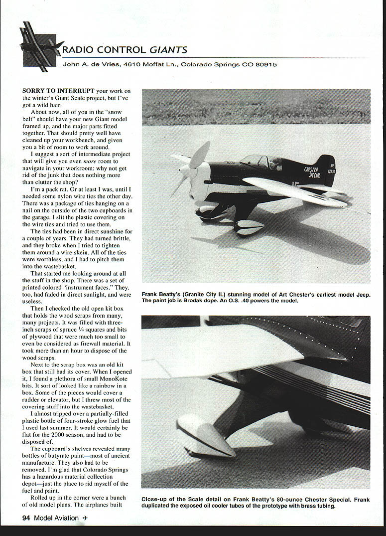
Old friend Frank Beatty of Granite City, IL has come up with another gem: a model of the Chester Special (aka Chester's Jeep), powered by an O.S. .40. The beautiful green-and-yellow model weighs about 80 ounces, spans 43 inches, and is 37 inches long.
One big advantage of modeling air racers of the 1930s is that even in the larger scales, the models are a reasonable size. Even a 1/4-scale version of one of the pylon polishers with a 20-foot wingspan works out to be a 60-inch-span model.
Frank was fascinated by the earliest version of Art Chester's racer, since it had a set of oil-cooler tubes exposed on the left side of the fuselage. He simulated them with brass tubing that is visible in the close-up photo. Frank used Sig Koverall and Brodak dopes to duplicate the color scheme.
However, two ugly problems reared their heads when Frank went to fly the model.
Five ounces of lead inside the cowling cured the tail-heavy problem, but the other was more difficult to solve.
Using the scale openings in the cowling, Frank learned that there wasn't enough cooling air reaching the engine. Solution: a nonscale opening was carved in the bottom of the cowl to let the hot air out. It's almost invisible, and it keeps the O.S. cool and not prone to quit.
Frank's next project will be the Curtiss CR-2 biplane racer. It will have a .46 engine for power, but there's a scale feature on the CR-2 that will be hard to duplicate: the prototype featured a skin radiator that covered the top of the upper wing with brass cooling tubing. Frank has decided that the corrugated sheet plastic available as model railroad construction material will be just the ticket.
However, he does have a problem: none of the documentation drawings that he's been able to assemble show the height of the skin radiator "bumps," or their spacing. If you have a drawing that details these scale dimensions, let me know, and I'll pass the word on to Frank.
Aircraft designers have had a ball trying to minimize the drag of the radiators that are necessary when a model is powered by a "water-cooled" engine. The quotes are necessary because most liquid-cooled engines, particularly the later versions, used ethylene glycol (Prestone®) mixed with water as the cooling fluid.
From the Wrights onward, there have been many solutions to the engine-cooling problem. The Wrights used a vertical radiator at the leading edge of their Flyer's wing. Early German aircraft were equipped with a wind-off radiator perched atop the Argus or Mercedes engine.
Glenn Curtiss probably had the best solution to the radiator location problem. He mounted it automobile fashion, directly behind the propeller on the JN-4 Jenny. The Fokker D.VII followed that pattern.
The radiators moved up and down during the 1920s. On the Curtiss P-6E, it was located on the bottom of the fuselage. On the Pietenpol, it was stuck atop the fuselage, and it really blocked the pilot's forward vision. This was a bad place because a hole in the radiator would spray steaming fluid right into the pilot's face.
Some aircraft had two radiators, one on each side of the fuselage, and the Alexander Eaglerock perched its radiator beneath the fuselage, but on struts or brackets.
In World War II, there were more valiant attempts to streamline the coolers. The P-40 had it in the nose, directly behind the propeller. The Spitfire and the Me 109 solved the problem by positioning two aerodynamic radiator installations—one beneath each wing panel. The liquid-cooled Mustang's fuselage was designed to accommodate the engine and oil cooler as part of the lower fuselage, under the wing and ahead of the cockpit.
From the modeling viewpoint, most of the radiators can be simulated using the brass screening material available from model railroad shops. Even common aluminum screening can be used—particularly if the radiator was enclosed in some sort of streamlined housing.
The radiators on Giant Scale models should be designed to permit air to flow through without restriction. The lumpy radiator on the bottom of the Hurricane's wing center section will produce a bunch of drag if it's stopped up by a fake, unpenetrable radiator screen.
Since scale radiator installations are so visible on a model, a great deal of care must be taken in their design. They've got to look good, but not affect a model's flight characteristics. Thank goodness for P-40s and Typhoons; their radiator airscoops are ideally arranged to air-cool an inverted model engine, and still look scale!
I'll let you get back to your millennium Giant Scale project. Hope it turns out to be everything you expect. Back with you all in the March issue.
MA
Transcribed from original scans by AI. Minor OCR errors may remain.

