
ESC governors
Author
Chris Mulcahy [email protected]
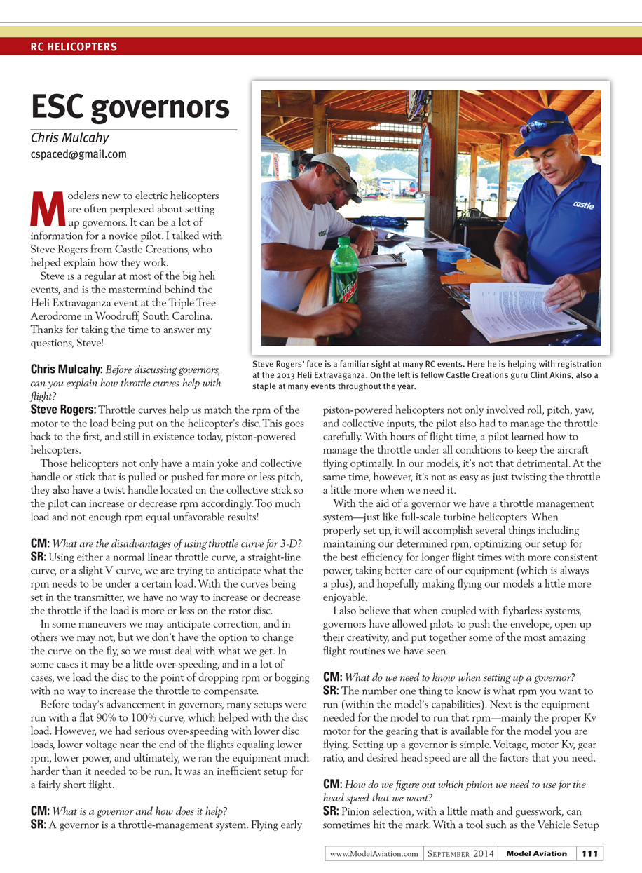
Modelers new to electric helicopters are often perplexed about setting up governors. It can be a lot of information for a novice pilot to take in at once. I talked with Steve Rogers from Castle Creations, who helped explain how they work.
Steve is a regular at most of the big heli events, and is the mastermind behind the Heli Extravaganza event at the Triple Tree Aerodrome in Woodruff, South Carolina. Thanks to Steve for taking the time to answer my questions.
Interview with Steve Rogers
Chris Mulcahy: Before discussing governors, can you explain how throttle curves help with flight?
Steve Rogers: Throttle curves help us match the rpm of the motor to the load being put on the helicopter’s disc. This goes back to the first—and still in existence today—piston-powered helicopters.
Those helicopters not only have a main yoke and collective handle or stick that is pulled or pushed for more or less pitch, they also have a twist handle located on the collective stick so the pilot can increase or decrease rpm accordingly. Too much load and not enough rpm equal unfavorable results!
Chris Mulcahy: What are the disadvantages of using throttle curve for 3-D?
Steve Rogers: Using either a normal linear throttle curve, a straight-line curve, or a slight V curve, we are trying to anticipate what the rpm needs to be under a certain load. With the curves being set in the transmitter, we have no way to increase or decrease the throttle if the load is more or less on the rotor disc.
In some maneuvers we may anticipate correction, and in others we may not, but we don’t have the option to change the curve on the fly, so we must deal with what we get. In some cases it may be a little over-speeding, and in a lot of cases, we load the disc to the point of dropping rpm or bogging with no way to increase the throttle to compensate.
Before today’s advancement in governors, many setups were run with a flat 90% to 100% curve, which helped with the disc load. However, we had serious over-speeding with lower disc loads, lower voltage near the end of flights equaling lower rpm, lower power, and ultimately we ran the equipment much harder than it needed to be run. It was an inefficient setup for a fairly short flight.
Chris Mulcahy: What is a governor and how does it help?
Steve Rogers: A governor is a throttle-management system. Flying early piston-powered helicopters not only involved roll, pitch, yaw, and collective inputs, the pilot also had to manage the throttle carefully. With hours of flight time, a pilot learned how to manage the throttle under all conditions to keep the aircraft flying optimally.
In our models, it’s not that detrimental. At the same time, however, it’s not as easy as just twisting the throttle a little more when we need it. With the aid of a governor we have a throttle management system—just like full-scale turbine helicopters. When properly set up, it will accomplish several things including:
- maintaining our determined rpm,
- optimizing our setup for the best efficiency for longer flight times with more consistent power,
- taking better care of our equipment,
- and making flying our models more enjoyable.
I also believe that when coupled with flybarless systems, governors have allowed pilots to push the envelope, open up their creativity, and put together some of the most amazing flight routines we have seen.
Chris Mulcahy: What do we need to know when setting up a governor?
Steve Rogers: The number one thing to know is what rpm you want to run (within the model’s capabilities). Next is the equipment needed for the model to run that rpm—mainly the proper Kv motor for the gearing that is available for the model you are flying.
Setting up a governor is simple. The factors you need are:
- voltage,
- motor Kv,
- gear ratio,
- desired head speed.
Chris Mulcahy: How do we figure out which pinion we need to use for the head speed that we want?
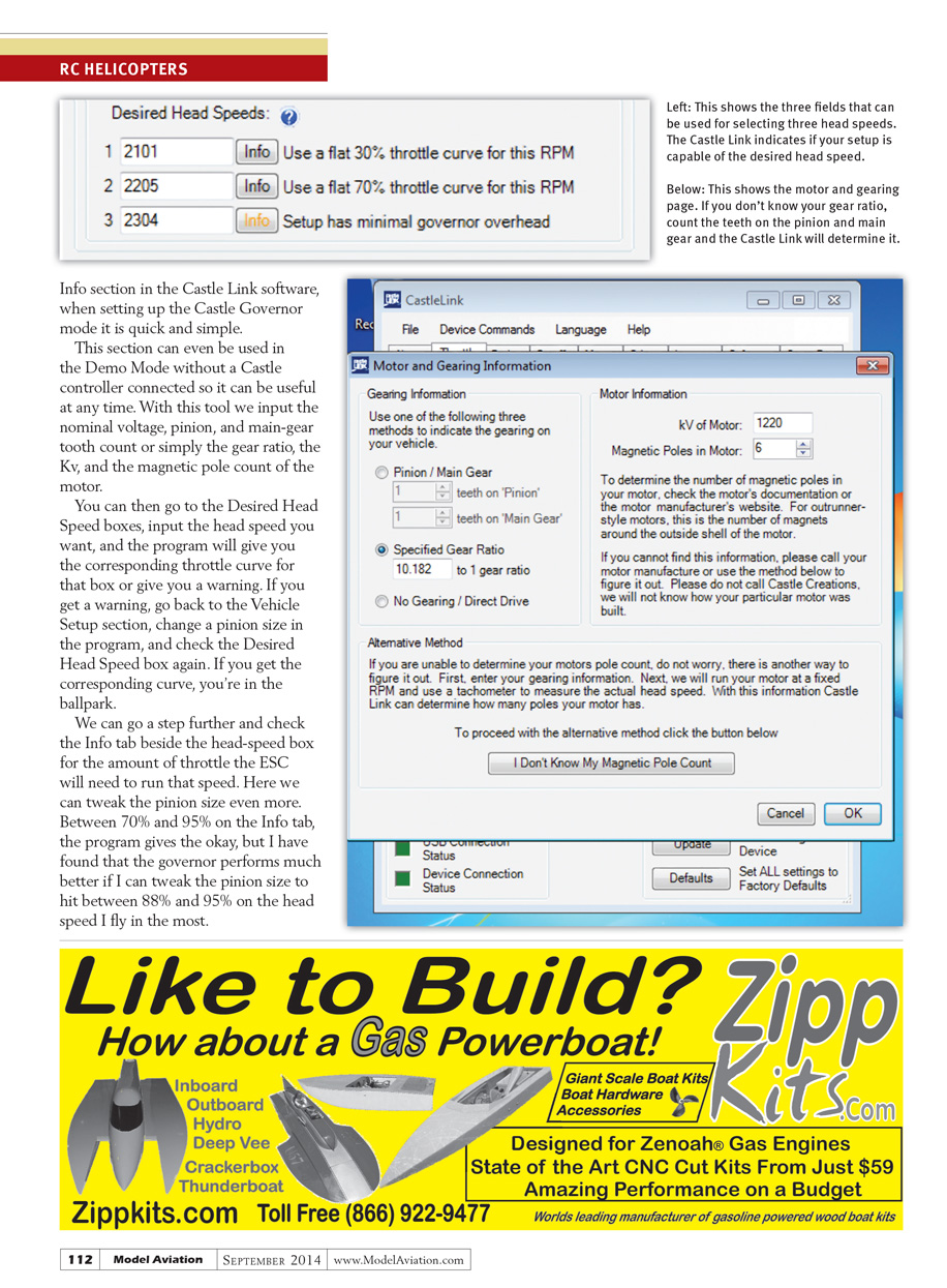
Steve Rogers: Pinion selection, with a little math and guesswork, can sometimes hit the mark. With a tool such as the Vehicle Setup Info section in the Castle Link software, when setting up the Castle Governor mode it is quick and simple.
This section can even be used in Demo Mode without a Castle controller connected, so it can be useful at any time. With this tool we input the nominal voltage, pinion, and main-gear tooth count or simply the gear ratio, the Kv, and the magnetic pole count of the motor.
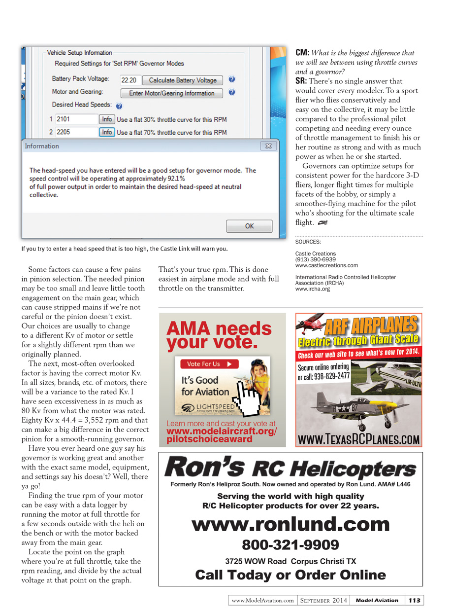
You can then go to the Desired Head Speed boxes, input the head speed you want, and the program will give you the corresponding throttle curve for that box or give you a warning. If you get a warning, go back to the Vehicle Setup section, change a pinion size in the program, and check the Desired Head Speed box again. If you get the corresponding curve, you’re in the ballpark.
We can go a step further and check the Info tab beside the head-speed box for the amount of throttle the ESC will need to run that speed. Here we can tweak the pinion size even more. Between 70% and 95% on the Info tab, the program gives the okay, but I have found that the governor performs much better if I can tweak the pinion size to hit between 88% and 95% on the head speed I fly most often.
Some factors can cause a few pains in pinion selection. The needed pinion may be too small and leave little tooth engagement on the main gear, which can cause stripped mains if we’re not careful—or the pinion may not exist. Our choices are usually to change to a different Kv motor or settle for a slightly different rpm than we originally planned.
The next, most-often overlooked factor is having the correct motor Kv. In all sizes, brands, etc. of motors, there will be a variance to the rated Kv. I have seen excessiveness in as much as 80 Kv from what the motor was rated. Eighty Kv × 44.4 = 3,552 rpm and that can make a big difference in the correct pinion for a smooth-running governor.
Have you ever heard one guy say his governor is working great and another with the exact same model, equipment, and settings say his doesn’t? Well, there you go!
Finding the true rpm of your motor can be easy with a data logger by running the motor at full throttle for a few seconds outside with the heli on the bench or with the motor backed away from the main gear.
Locate the point on the graph where you’re at full throttle, take the rpm reading, and divide by the actual voltage at that point on the graph. That’s your true rpm. This is done easiest in airplane mode and with full throttle on the transmitter.
Chris Mulcahy: What is the biggest difference that we will see between using throttle curves and a governor?
Steve Rogers: There’s no single answer that would cover every modeler. To a sport flier who flies conservatively and easy on the collective, it may be little compared to the professional pilot competing and needing every ounce of throttle management to finish his or her routine as strong and with as much power as when he or she started.
Governors can optimize setups for consistent power for the hardcore 3-D fliers, longer flight times for multiple facets of the hobby, or simply a smoother-flying machine for the pilot who’s shooting for the ultimate scale flight.
SOURCES
- Castle Creations
(913) 390-6939 www.castlecreations.com
- International Radio Controlled Helicopter Association (IRCHA)
Transcribed from original scans by AI. Minor OCR errors may remain.

