
Preparing for the flying season
by Jim Hiller [email protected]
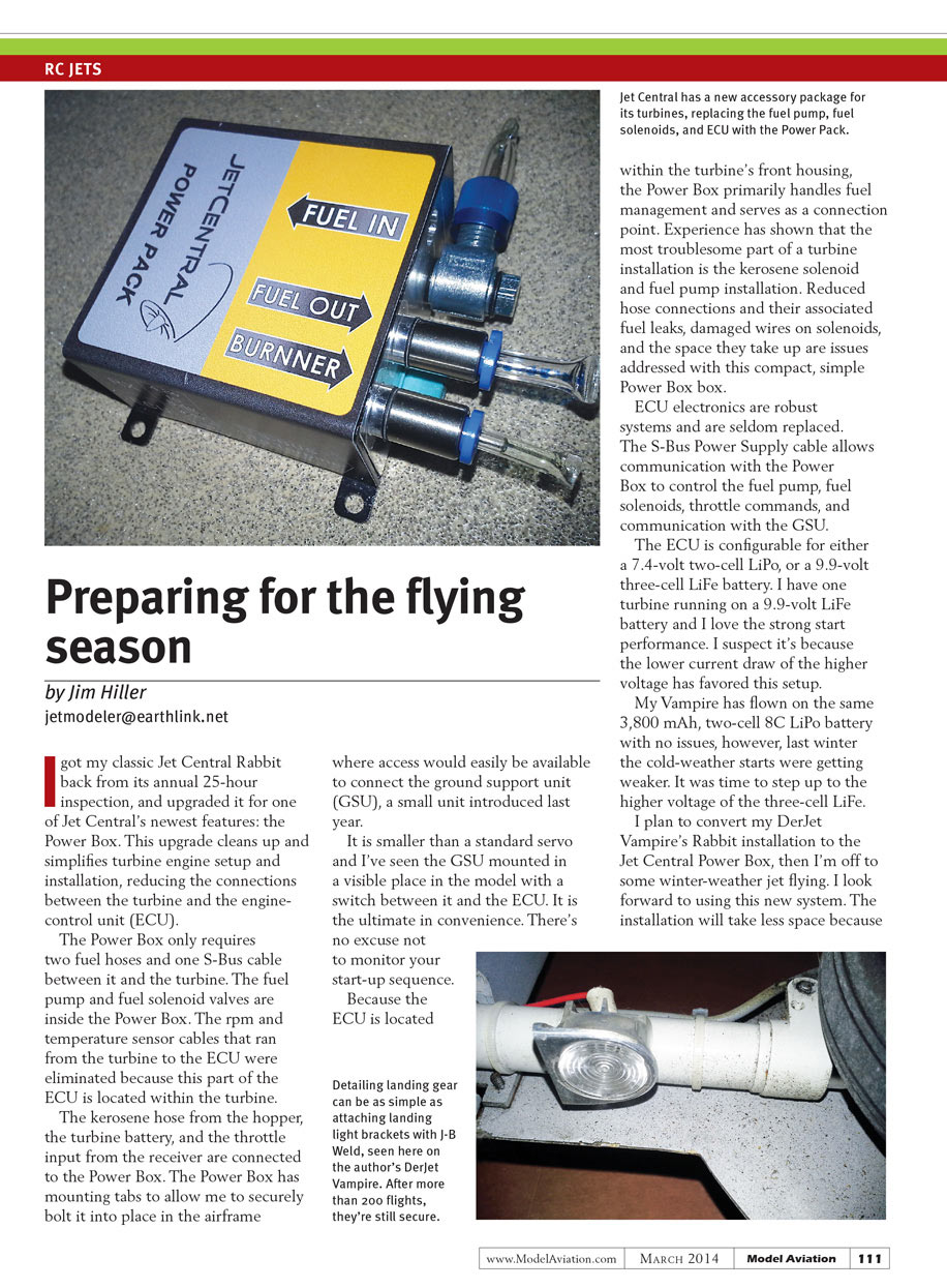
I got my classic Jet Central Rabbit back from its annual 25-hour inspection and upgraded it for one of Jet Central’s newest features: the Power Box. This upgrade cleans up and simplifies turbine engine setup and installation, reducing the connections between the turbine and the engine-control unit (ECU).
The Power Box requires only two fuel hoses and one S‑Bus cable between it and the turbine. The fuel pump and fuel solenoid valves are inside the Power Box. The rpm and temperature sensor cables that used to run from the turbine to the ECU were eliminated because that portion of the ECU is now located within the turbine.
The kerosene hose from the hopper, the turbine battery, and the throttle input from the receiver are connected to the Power Box. The Power Box has mounting tabs so I can securely bolt it into place in the airframe where access is easily available to connect the ground support unit (GSU), a small unit introduced last year.
The GSU is smaller than a standard servo; I’ve seen it mounted in a visible place in the model with a switch between it and the ECU. It’s the ultimate in convenience—there’s no excuse not to monitor your start-up sequence.
Because the ECU is located within the turbine’s front housing, the Power Box primarily handles fuel management and serves as a connection point. Experience has shown that the most troublesome parts of a turbine installation are the kerosene solenoid and fuel pump. Reduced hose connections (and their associated leaks), fewer damaged solenoid wires, and the space saved are all benefits addressed by this compact, simple Power Box.
ECU electronics are robust systems and are seldom replaced. The S‑Bus power-supply cable allows communication with the Power Box to control the fuel pump, fuel solenoids, throttle commands, and to interface with the GSU.
The ECU is configurable for either a 7.4‑volt two‑cell LiPo or a 9.9‑volt three‑cell LiFe battery. I have one turbine running on a 9.9‑volt LiFe battery and I love the strong start performance. I suspect the lower current draw at the higher voltage favors this setup.
My Vampire has flown on the same 3,800 mAh two‑cell 8C LiPo battery with no issues; however, last winter the cold-weather starts were getting weaker. It is time to step up to the higher voltage of the three‑cell LiFe.
I plan to convert my DerJet Vampire’s Rabbit installation to the Jet Central Power Box, then I’m off to some winter-weather jet flying. The installation will take less space because the Power Box replaces the fuel system. Come to think of it, even the ECU mount is no longer necessary. This will be easier to convert than to reinstall all that it replaces. I love the new advances in Jet Central's turbine packaging.
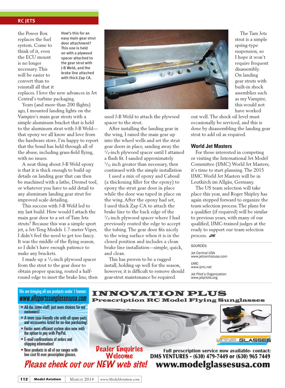
Years ago (and after more than 200 flights) I mounted landing lights on the Vampire's main gear struts with a simple aluminum bracket that I bonded to the aluminum strut with J‑B Weld—the epoxy we all know from the hardware store. I’m happy to report that the bond has held through all the abuse, including grass‑field flying, with no issues.
A neat thing about J‑B Weld epoxy is that it’s thick enough to build up details on landing gear that can then be machined with a lathe, Dremel tool, or whatever you have to add scale detail to any aluminum landing gear strut.
This success with J‑B Weld led to my last build: how would I attach the main gear door to a set of Tam Jets struts? Because this was a simple sport jet—a Jet‑Teng Models 1.7‑meter Viper—I didn't feel the need to get too fancy. It was the middle of the flying season, so I didn't have the patience to make any brackets.
I made a 1/4‑inch plywood spacer from the strut to the gear door to obtain proper spacing, routed a half‑round edge to inset the brake line, then used J‑B Weld to attach the plywood spacer to the strut.
After installing the landing gear in the wing, I raised the main gear into the wheel wells and set the strut gear doors in place, sanding away the 1/4‑inch plywood spacer until I attained a flush fit. I sanded approximately 1/32 inch more than necessary, then continued with the simple installation.
I used a mix of epoxy and Cabosil (a thickening filler for epoxy) to bond the strut gear door in place while the door was taped on the wing. After the epoxy had set, I used thick Zap CA to attach the brake line to the back edge of the 1/4‑inch plywood spacer where I had routed the channel to accept the tubing. The gear door fits nicely to the wing surface when closed and includes a clean brake line installation—simple, quick, and tidy.
This has proven to be a rugged installation, holding up well for the season. However, it is difficult to remove should gear‑strut maintenance be required.
The Tam Jets strut is a simple spring‑type suspension, so I hope it won't require frequent disassembly. On landing gear struts with built‑in shock assemblies, such as my Vampire, this method would not have worked well. The shock oil level must occasionally be serviced, and that requires disassembling the landing gear strut to add oil.
World Jet Masters
For those interested in competing or visiting the International Jet Model Committee (IJMC) World Jet Masters, it's time to start planning. The 2015 IJMC World Jet Masters will be in Leutkirch im Allgäu, Germany.
The U.S. team selection will take place this year, and Roger Shipley has again stepped forward to organize the team selection process. Plans for a qualifier (if required) will be similar to previous years, with many of our qualified, IJMC‑trained judges ready to support the selection process.
Sources
- Jet Central USA — www.jetcentralusa.com
- IJMC — www.ijmc.net
- Jet Pilot's Organization — www.jetpilots.org
Transcribed from original scans by AI. Minor OCR errors may remain.

