
RADIO CONTROL PYLON RACING
Duane Gall, 1267 S. Beeler Ct., Denver CO 80231; E-mail: [email protected]
QUICKIE 500 Construction, Part Two
Last month I began this series with assembly hints for two typical Q-500 kits—one with a fiberglass fuselage and the other with a wooden fuselage. The fiberglass model is the Matney Models Mad Dog, and the balsa kit is the X-1 design by Craig Farthing.
This month I'll discuss wing assembly.
Since the Q-500 rules allow very little variation in wing design, this description will be generic.
The only significant differences between the Mad Dog and the X-1—or between any two Quickie designs employing balsa-sheeted foam wings—are in the airfoil, the size and placement of the ailerons, and the fashion statement made by the designer's choice of wingtips.
The essence of a Quickie wing is a 48 x 10-inch slab of white polystyrene foam, with sheets of 1/16" balsa bonded to the top and bottom.
When I started flying radio control (RC), foam wings were a new and exotic development. They are more common nowadays, but foam wings are still not mainstream—except among scratchbuilders.
There's nothing to be afraid of, though. Besides the foam cores and balsa skins, all you really need are:
- A flat workbench that is strong enough to stand on
- A lightweight, slow-curing epoxy (such as Z-Poxy) to use as an adhesive
- A spatula, or similar device, to spread the epoxy very thin on the balsa skins (a credit card works especially well)
- 100 to 300 pounds of books, bricks, or back issues of model-aircraft magazines
An alternative to a mountain of books is vacuum-bagging. Composite wing construction involving foam and balsa or other "sandwich" combinations is no longer new. The technology has advanced to the point where an enterprising modeler can purchase a vacuum-bag setup that uses atmospheric pressure to press the components together until the epoxy cures.
Vacuum-bagging is helpful for our purposes, but not necessary. It's helpful because if your model's internal parts (full-depth spars, carbon-fiber strips, dowels for hold-down bolts, etc.) cause lumps in the surface of the core or the skin, the enormous pressure generated by the vacuum pump will crush the balsa and/or the foam around the bumps.
Vacuum-bagging eliminates gaps in the epoxy bond between the core and the skin, and it provides good contact everywhere.
If bumps show through on the outside, block-sand the balsa to get rid of them. However, if you make everything nice and smooth where the balsa meets the core, a pile of bricks on top of the assembly will provide adequate pressure to give good contact.
Your Q-500 wing can be reinforced with 1-inch-wide, 50,000-strand carbon-fiber tow (loose fibers you saturate with epoxy and smooth onto the inside of the balsa skin using the credit card) as your spar material, rather than the rigid, premade strips.
The strips have a measurable thickness that may lift the skin away from the core, causing a void next to the strip. But the loose tow will taper down and blend into the balsa at the edges, resulting in a barely perceptible bump.
Whichever type of carbon fiber you use, place it spanwise on the top and bottom of the wing, at the thickest part of the airfoil—approximately three inches back from the leading edge.
If you do invest in a vacuum pump, one of the cheap nonadjustable types is fine. Most will draw five to seven inches of mercury at sea level, which when multiplied by 500 square inches, is roughly equivalent to parking a Subaru Legacy on top of your wing. (Except unlike the Subaru, it won't collapse your workbench!)
If you use white foam for the cores, three inches of vacuum is almost all the wings can take without permanently compressing and distorting the airfoil.
Assembly sequence
Assuming you are building a shoulder-wing airplane with no dihedral (this describes the Mad Dog, the X-1, and most Q-500 designs), tack-glue the foam cores together at the middle to make a 48-inch-long panel.
This is not a load-bearing joint, so a few drops of five-minute epoxy will do. Take care to align the panels perfectly. Do this by weighing them down lightly in one of the bottom "shucks" (scrap foam pieces, supplied with the cores), with waxed paper underneath the glue joint. Join the shucks at the middle, and put the bottom shuck assembly on the strongest, flattest part of your workbench.
Assemble two wing skins from 48-inch-long 1/16" light-balsa sheet. If you use four-inch-wide planks, you'll need three for the top and three for the bottom.
True up the edges with a sharp #11 X-Acto™ or single-edge razor blade and a straightedge, then join the pieces edgewise with masking tape. No glue! The masking tape goes on what will be the outside of the finished wing, to be peeled off later.
The epoxy will wick up into the seams during the bonding process, and will stop when it hits the masking tape. That will give you a clean outside surface with crisp, sandable epoxy seams.
If the model you are building does not have add-on tips, but instead comes with cores that are longer than 48 inches (such as the Mad Dog and X-1), you will need to extend the tips of the wing skins a couple inches. This requires a little more preparation, but it saves work in the long run.
Using a 30° x 60° x 90° triangle, make a 30° cut in the end of each 48-inch piece, then splice on another piece to make skins approximately 53 inches overall.
Alternate the scarfed ends, so you'll have two on one tip and one on the other; the two scarf joints on one tip should be separated by the nonscarfed piece.
The width of the sheeting will be roughly 10 inches. I leave it slightly extra wide, so I can use a dowel for the leading edge, with the sheeting extending over the dowel on the top and bottom.
That way, rather than gluing a balsa leading edge on the front and trying to sand it to the right radius and keep it straight, I can sand down through the front edge of the sheeting to the dowel.
Depending on the leading-edge radius of the airfoil you're using, this can work quite handily. If you use this method, don't be afraid to brush extra epoxy onto the dowel for a good, hard bond. You may also want to "pinch" the sheeting around the dowel with small pieces of masking tape or clothespins as the assembly is curing.
The last step before assembly is to prepare the carbon-fiber tow and the fiberglass cloth center-section reinforcement. I put the glass cloth inside the wing, between the foam core and the balsa skin.
Use three layers of 2-ounce cloth for each skin (top and bottom), with each layer cut to a different spanwise width. One layer will be slightly wider than the fuselage, the next layer will be approximately twice that width, and the last layer will be roughly 15 inches wide.
Mix approximately three ounces of epoxy resin in a paper cup. Dribble approximately one ounce onto each balsa skin, and use the spatula or the credit card to spread it out very thin over the entire surface.
Add the three layers of glass cloth one at a time, using a disposable brush to apply a little more epoxy to each layer as you go. Add the carbon-fiber tow (running spanwise, at the high point of the airfoil), and work a small amount of epoxy into the fibers.
Remove as much excess epoxy as you can with the credit card. The glass and carbon fiber should be wetted out, but not dripping wet.
Place the bottom skin in the bottom shuck, epoxy-side up. Use pins or small pieces of masking tape to keep the skin from sliding around.
Put the foam core on top of the skin, and carefully align it directly above the shuck. This way, when the whole assembly is weighted down, the curvature of the shuck will apply pressure evenly to the bottom surface of the airfoil with the bottom skin in between. Pins or small pieces of tape will help keep everything in register.
Add the top skin, epoxy-side down. Add the top shuck above that. If you're doing the dowel-leading-edge method, make sure the dowel is properly pinched between the top and bottom sheeting, and that there's plenty of epoxy there.
Load the whole affair up with bricks and books, snap off those rubber gloves, and let it sit overnight.
Fancy aileron tricks
The Mad Dog uses conventional aileron torque rods. Make them from 1/8" steel wire if you are going to power the model with a Nelson or a Jett engine. Your model may develop high-speed flutter with smaller wire, and you can't do anything about it if the torque rods are too flexible.
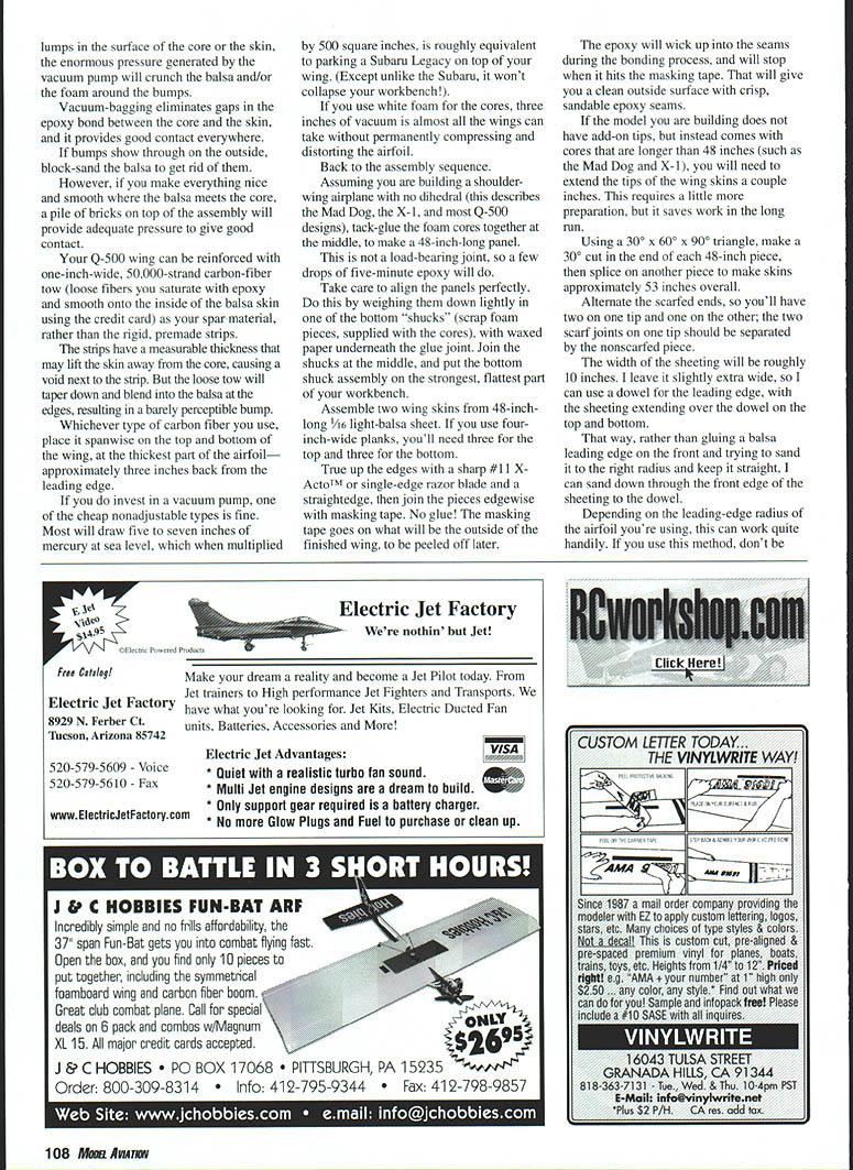
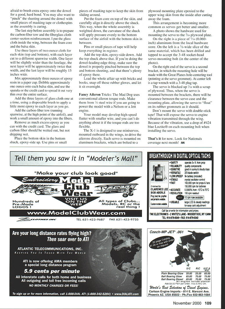
The X-1 is designed to use mini servos, mounted outboard in the wings, to drive the ailerons directly. Each servo is mounted on aluminum brackets, which are bolted to a plywood mounting plate epoxied to the upper wing skin from the inside after cutting away the foam. This arrangement is becoming more common as servos get better and smaller.
A photo (not included here) shows the hardware used for mounting the servo to the 3/16" plywood plate. On the right is a piece of 1/16" (0.060-inch) aluminum from the local hardware store. On the left is a 7/8"-wide slice of the same material, which has been drilled and tapped to accept the 3-48 socket-head servo-mounting bolt.
On the right end of the servo is a second bracket, in which the mounting hole will be made with the Great Planes hole-centering tool (pointed at the servo grommet). At center left is a tap wrench with a 3-48 tap.
The servo is blocked up 1/16" with a scrap of plywood. Thus, when the servo is mounted between the brackets, there will be clearance between the servo case and the mounting plate, allowing the servo to "float" on its rubber grommets as it should.
Don't mount the servo with double-stick tape! That will expose the servo to engine vibration transmitted through the wing. Because of the vibration, use a drop of #424 blue Loctite on each mounting bolt when installing the servo.
That's it for now. Look for Nationals coverage next month! MA
Transcribed from original scans by AI. Minor OCR errors may remain.

