
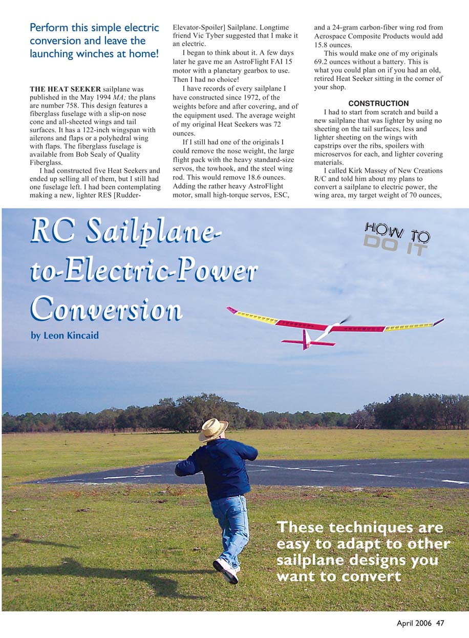
RC Sailplane-to-Electric-Power Conversion
by Leon Kincaid
THE HEAT SEEKER sailplane was published in the May 1994 MA; the plans are number 758. This design features a fiberglass fuselage with a slip-on nose cone and all-sheeted wings and tail surfaces. It has a 122-inch wingspan with ailerons and flaps or a polyhedral wing with flaps. The fiberglass fuselage is available from Bob Sealy of Quality Fiberglass.
I had constructed five Heat Seekers and ended up selling all of them, but I still had one fuselage left. I had been contemplating making a new, lighter RES (rudder-elevator-spoiler) sailplane. Longtime friend Vic Tyber suggested that I make it an electric.
A few days later he gave me an AstroFlight FAI 15 motor with a planetary gearbox to use. Then I had no choice!
I have records of every sailplane I have constructed since 1972, of the weights before and after covering, and of the equipment used. The average weight of my original Heat Seekers was 72 ounces.
If I still had one of the originals I could remove the nose weight, the large flight pack with the heavy standard-size servos, the towhook, and the steel wing rod. This would remove 18.6 ounces. Adding the rather heavy AstroFlight motor, small high-torque servos, ESC, and a 24-gram carbon-fiber wing rod from Aerospace Composite Products would add 15.8 ounces.
This would make one of my originals 69.2 ounces without a battery. This is what you could plan on if you had an old, retired Heat Seeker sitting in the corner of your shop.
CONSTRUCTION
I had to start from scratch and build a new sailplane that was lighter by using:
- no sheeting on the tail surfaces,
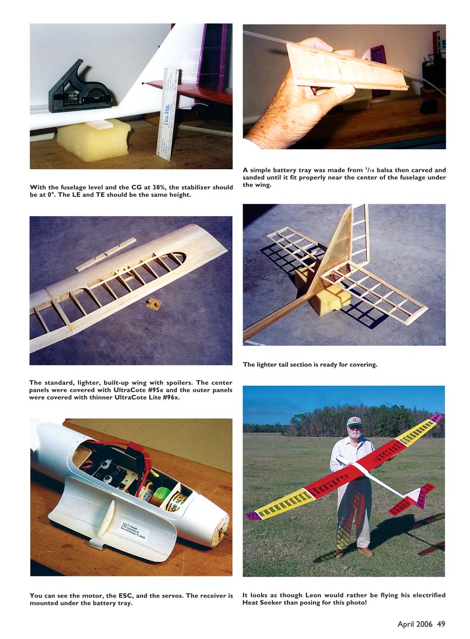
- less and lighter sheeting on the wings with capstrips over the ribs,
- spoilers with microservos for each side,
- lighter covering materials.
I called Kirk Massey of New Creations R/C and told him about my plans to convert a sailplane to electric power, the wing area, and my target weight of 70 ounces. He recommended a propeller size, the amps and watts I should expect to read, and the climb angle. As it ended up, he was right on. After completion the Heat Seeker weighed 68 ounces ready to fly with battery.
If you are starting from scratch, you can save some time tapering the wing and stabilizer ribs by using Anderson's airfoil program. Use airfoil K3311 for the wing and NACA 65-A008 for the stabilizer. These techniques are easy to adapt to other sailplane designs you want to convert.
With the fuselage level and the CG at 38%, the stabilizer should be at 0°. The wing will be roughly 1-1/2° positive incidence. The LE and TE of the stabilizer should be the same height.
Canopy and nose modifications
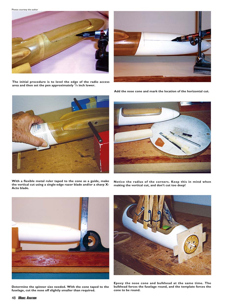
- With a flexible metal ruler taped to the cone as a guide, make the vertical cut using a single-edge razor blade and/or a sharp X-Acto blade. Notice the radius of the corners; don't cut too deep.
- Determine the spinner size needed. With the cone taped to the fuselage, cut the nose off slightly smaller than required. The cone will probably go back another 1/32–1/16 inch when off. Re-tape and sand the nose for the correct spinner outside diameter (OD) and the required right thrust and downthrust.
- With the cone added, mark the location of the horizontal cut for the canopy. Level the edge of the radio access area and set the pen about 1/4 inch lower to represent the bottom of the canopy cover. Alternatively, measure up from the building board and make two tick marks and draw the horizontal line on both sides.
- Measure from the small shoulder on the fuselage where the edge of the cone would be to the back and forward edge of the new canopy cover, allowing at least 1/8 inch overlap in the rear and approximately 3/16 inch in the front. Transfer these measurements to the top of the cone, wrap a thin scale around the cone, and draw the rear and forward edges down to the horizontal lines.
- Cut out the canopy cover using a flexible metal scale taped to the cone as a straightedge and a single-edge razor blade and sharp X-Acto blade. Optionally make a thin phenolic template and add a radius to each corner for a neater look.
Spinner and thrust angles
- With the fuselage sitting on a level building board and a level on top of the tailboom, set the CG to 38%. With a square against the nose, every 1/32-inch gap at the bottom of the nose represents 1° of downthrust (e.g., 1/16 inch = 2°, 3/32 inch = 3°). I used 2° right thrust, which worked out perfectly in side-thrust. I used only 2° downthrust; it required holding a bit more down elevator in the climb than ideal, but it was acceptable.
- The secret is to sand the nose to the correct OD and thrust angles at the same time. If done correctly, you can add the motor-mounting bulkhead flush with the forward end of the fuselage and bolt the motor to it.
Bulkhead and cone installation
- Before adding the bulkhead, grind or sand away the internal ribbon (about 1 inch wide top and bottom) roughly 1/4 inch just inside the cone and fuselage. This evens wall thickness so the round bulkhead will force the slightly egg-shaped fuselage to be round.
- Because there is usually a small gap between the fuselage and the cone, and the cone can be slightly egg-shaped, construct a thin-plywood template with a hole slightly larger than the spinner OD. Force the template over the outside of the cone during assembly to make the outside round. I added lugs to pull the template back tight with rubber bands, but mine stuck well enough without them.
- Epoxy the cone and bulkhead together at the same time. Don't overdo the adhesive. Add epoxy around the rear of the cone, the canopy area, on the bulkhead during installation, and generously around the nose between the fuselage and cone. Use clothespins or rubber bands as needed and a Q-tip to wipe away any excess epoxy so the canopy will fit back in its original position after drying.
- Counterbore the bulkhead for the mounting screws to clear the spinner.
Ventilation and air inlets
- You need adequate ventilation. I left the rear opening of the fuselage tailboom open and, with the rudder blocking the air exit, used a Dremel with a small round router bit to scallop a bit on each side of the rudder centerline to help the air exit.
- I also drilled three 1/8-inch holes in or under each wing fillet and elongated them with a small round file to assist venting. This position does not weaken the fuselage and is a good low-pressure area.
- Because I used a planetary gearbox and a Turbo spinner with an air inlet in the center, there was adequate space around the mounting bulkhead to drill air-inlet holes before installation. A larger-OD gearbox motor with a normal spinner might require air inlets added to each side of the fuselage.
Battery tray
- I made a simple battery tray from 1/16 balsa and carved and sanded it to fit near the center of the fuselage under the wing. After fitting, I added 1/8-inch cross-grain balsa to support the battery weight and refit the tray. I added 1/8-inch square balsa near the outside edge to guide the pushrods.
- For battery installation I lay a thin-plywood "pizza paddle" roughly 1-1/4 inches wide over the Velcro and slid the battery in over the paddle. Once the battery was in place I pulled the paddle out. To remove the battery I slide the paddle between the Velcro to separate it and the battery slides out.
Radio Installation
I used two small, strong JR 341 servos for the rudder and elevator. They are strong and light and sit low, allowing installation of a 1700 mAh stick-type battery over the servos to the battery tray. I used FMA Direct S-80 servos in each wing for the spoilers.
I installed a JES500 speed control. I planned to use a small Hitec 555 receiver under the battery box, but there was adequate room for a full-size Futaba receiver with foam between the two. I used a Futaba 7UAF transmitter.
Flying
After installing the battery, the CG was right on 38%. I have stopped trying to hand-glide a model before flying it; that is a good way to break something. I do my trimming in the air, where it is safe.
On the first flight I let the model fly straight ahead at half power for a second or so to make sure nothing was going wrong, and then I gave it full power. I couldn't believe the climb angle. I did have to hold down elevator in the climb, but as soon as the power was cut no change was needed in the trims. The design proved to be stable and effective.
The second flight lasted slightly longer than an hour. For landing I put the spoilers on the landing-gear switch; the Futaba flap knob is too difficult to find and rotate. The quick action of the gear switch does not seem to be a problem.
Power systems and weights
- I was happy with a 16-ounce Ni-Cd pack initially. Later I tried a Thunder Power three-cell, 2100 mAh Li-Poly pack. The 3S 2100 is the minimum size to use with this motor, but I don't abuse it. I broke it in per the instructions and it works super. With the Li-Poly my 68-ounce Heat Seeker weighed 57 ounces. I am thinking it would be even lighter with a brushless motor and a smaller propeller.
Other conversions
- Ray Gebaur converted his 9-year-old Heat Seeker to electric power with a new AstroFlight 05 motor. It flies great (and is heavier). Vic Tyber says he is going to convert his Heat Seeker to electric as soon as I can cut his canopy out.
If you would like to start from scratch, Bob Sealy still makes the fuselages for $55 including postage. I thought I would never make or fly any electrics larger than my Speed 400- and GWS-powered old-time FF designs, but this was a ball.
Leon Kincaid [email protected]
Sources
- Aerospace Composite Products
357 Stealth Ct. Livermore, CA 94551 (800) 811-2009 www.acp-composites.com
- Quality Fiberglass — Bob Sealy
2530 Zeb Warren Rd. Cookeville, TN 38501 (931) 526-4770
- New Creations R/C — Kirk Massey
Box 496 Willis, TX 77378 (936) 856-4630 www.newcreations-rc.com
- Chuck Anderson
Box 305 Tullahoma, TN 37388 (931) 455-6430 [email protected]
Transcribed from original scans by AI. Minor OCR errors may remain.

