


Setting up the heart and soul of your model
by John Glezellis [email protected]
In my last column, I explained how a pilot could change the response of an airplane to suit his or her particular needs. This month, I will continue to discuss how to obtain a proper setup for your aircraft.
In addition to the importance of having an airplane react in a preferred manner, it is equally important to examine the various radio programming and the linkage installation of the throttle servo.
Many will agree that the radio installation and functionality, as well as the engine, are the heart and soul of your model. I have helped many pilots program their airplanes only to find that some did not take the time to properly program settings that pertain to the throttle servo.
I will discuss which servo should be used for throttle control, the various programming functions I adjust for proper functionality of the servo (which include sub trims, adjustable travel volume, etc.), the need and use of two idle positions in a given flight, and review proper linkage installations.
You shouldn't have to worry about an inconsistent idle at any point during your flight. After all, a dead-stick approach can be the difference between first and last place in a competition! Without further delay, let's begin!
A Potential Problem
Typically, any maneuver that requires the throttle stick to be at idle can be problematic if the throttle servo and linkage are not properly set up. In the 2012 Basic schedule, maneuver six is a stall turn, which is also known as a Hammerhead; maneuver 10 is a one-and-a-half-turn positive spin. The engine could potentially quit while performing either of these maneuvers.
A pilot could have an idle that is set too low. Once the airplane is rotating, either at the top of the stall turn or during the spin, the engine may stop. The servo linkage may bind and result in an unpredictable idle position, which can also cause the engine to stop functioning. I have often seen it happen to others.
Please use this column as a guide for the throttle servo and the other linkages that are located on your airframe. Many of these principles are applicable to all servos.
Throttle Servo Selection
When someone asks me what servos I recommend for a competition-level aircraft, which can be 50cc and larger, I urge him or her to invest in a high-performance servo for all applications. The airplanes we fly are often expensive. Having a servo fail, even on the throttle, can be fatal for an aircraft.
Many manufacturers produce high-voltage servos. These servos take the voltage of a two-cell LiPo battery, which puts out approximately 8.4 volts on a fresh charge. If this is your choice, make sure that either the throttle servo is high-voltage, or that you use a voltage regulator for the throttle servo. Running a servo at a voltage higher than recommended by the manufacturer can harm the servo and/or shorten its lifespan.
Make sure that your servo centers properly and always comes back to the same end points. If it doesn't, make sure that the servo arm is properly secured on the servo output spline. If your servo features a metal output spline, use threadlocker for the servo screw that holds the servo arm in place. Regardless of whether or not your servo features a metal or plastic output spline, perform routine maintenance to ensure that the servo arm is properly secured. The threads on the output spline of a plastic-geared servo can strip, causing the servo screw to loosen and back out during flight. Make sure that all servo screws are properly secured before taking to the skies.
As with anything mechanical in nature, a servo can fail at any time for any reason. Maybe there was a cold solder joint within the servo that vibrated loose in flight, or maybe a servo gear stripped internally. If either of the two scenarios happened, the result could be catastrophic for your airplane. The engine may stop working at an rpm that is too high to land.
If you are new to the world of giant-scale aerobatics gas-powered models, a neat gadget to have is an ignition cutoff. Smart-Fly offers one that I have seen in many airplanes, and it adds approximately 0.3 ounces to your aircraft. This unit allows you to kill the engine any time while in flight—especially if you have a throttle servo fail—so you can safely land the aircraft.
Let's Look at Linkages
Installing a servo and linkages is simple and is outlined in most airplane assembly manuals. It is important to ensure there is no friction within the movement of the throttle linkage, and that it is properly supported.
Last year, I built a Hangar 9 Sukhoi SE and the Extra 300. Both require a lengthy throttle pushrod. With the Sukhoi, a throttle pushrod is inserted within a plastic tube and wood supports properly align the pushrod from the throttle servo to the throttle arm on the carburetor. This pushrod was long because the throttle servo was mounted next to the fuel tank. With differing amounts of throttle, the pushrod can't bend or flex because of these supports.
On the Hangar 9 Extra 300, the throttle servo is mounted on the motor box a few inches from the firewall. For pushrods, my first choice is to use a titanium turnbuckle whenever possible. However, the longest turnbuckle I found was 5 inches long, and I needed much more overall length.
I used a 4-40 threaded pushrod from Du-Bro and inserted it in a carbon sleeve. I used J-B Weld to secure the pushrod within the carbon tube and used two ball links to secure the pushrod to the throttle servo and the arm on the carburetor. No flex, guaranteed!
Study the motion of travel of the throttle servo arm and how it aligns with the corresponding arm on the carburetor. If you notice that the servo does not return to the same idle position, study the linkage setup to ensure there is no friction. Also, ensure that the servo is not trying to "drive" the pushrod to an angle that the carburetor doesn't allow.
Proper Programming 101
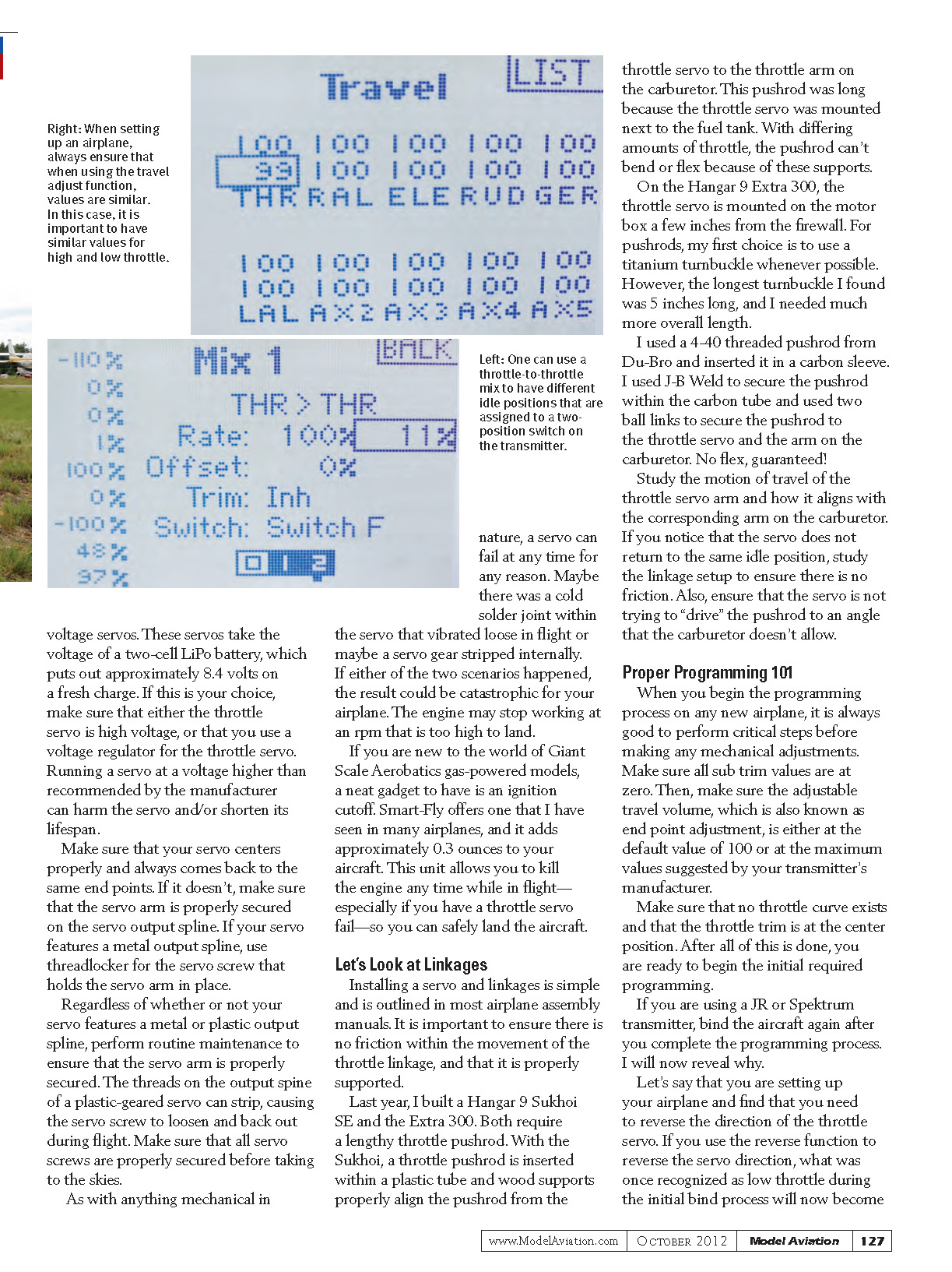
When you begin the programming process on any new airplane, it is always good to perform critical steps before making any mechanical adjustments. Make sure all sub-trim values are at zero. Then, make sure the adjustable travel volume, which is also known as end point adjustment, is either at the default value of 100 or at the maximum values suggested by your transmitter's manufacturer.
Make sure that no throttle curve exists and that the throttle trim is at the center position. After all of this is done, you are ready to begin the initial required programming.
If you are using a JR or Spektrum transmitter, bind the aircraft again after you complete the programming process. I will now reveal why.
Let's say that you are setting up your airplane and find that you need to reverse the direction of the throttle servo. If you use the reverse function to reverse the servo direction, what was once recognized as low throttle during the initial bind process will now become full throttle. If there are any issues with the transmitter signal in a given flight and the aircraft goes into failsafe, it will be at maximum power.
If the airplane is on the ground and you accidentally turn the transmitter off, it will switch to maximum power. Make sure you re-bind your aircraft once all servos are traveling in the proper direction.
Two Different Positions
I covered several programming techniques that I'll expand on. Although I do not use it, I have seen others utilize two different idle positions in a given flight. Some people use a landing idle and a flight idle, which are assigned to a two-position switch on the transmitter.
With the flip of a switch, you can have your aircraft idle down for landing. However, you won't have to worry about the engine stopping in a maneuver such as a spin or stall turn because you can use a higher idle—which is called your flight idle—after you're in the air.
If you go this route, don't use excessive flight idle. Use enough rpm so that the engine has a low idle, but one that slows down enough to stall the airplane for a proper spin entry. You don't want to give away easy points when competing!
This can be done using a programmable mix on your transmitter. Assign throttle as both the master and slave channel for the mix, resulting in what is called a throttle-to-throttle mix. Assign this mix to a switch of your choice.
Enter a value or values into the mix so that two different idle positions exist. The process is straightforward.
Final Thoughts
I urge you to always take your time and properly set up your aircraft. Many variables can cause one failure.
If your engine stops in flight, don't panic and remember to keep the airspeed up. If you feel that you will be unable to make the runway, observe your surroundings and try to find a smooth area to land your airplane. When landing, keep your wings level and stretch the approach. Balance your airspeed and apply a slight flare as the airplane is about to land, in an effort to minimize damage.
With time and practice, these survival instincts will become second nature. In the meantime, follow the principles outlined to achieve a reliable mechanical setup.
Until next time, fly hard!
SOURCES
- Du-Bro
(800) 848-9411 www.dubro.com
- Horizon Hobby Distributors
(800) 338-4639 www.horizonhobby.com
- International Miniature Aerobatic Club
- J-B Weld
(800) 529-3530 www.jbweld.net
- Smart-Fly
(480) 460-2652 www.smart-fly.com
Transcribed from original scans by AI. Minor OCR errors may remain.

