
Consistency is in the details
by John Glezellis [email protected]
When you enter the International Miniature Aerobatic Club (IMAC) competition scene, there is no doubt that endless hours will be spent at the flying field perfecting a given aerobatic sequence. An RC aerobatics pilot must concentrate on executing each maneuver to the best of his or her ability. Any inconsistency in the performance will only serve as a distraction and result in a possible downgrade by the judging panel.
You must also spend time in the workshop setting up and programming the competition aircraft. Throughout the years, I have seen many capable pilots experience difficulty in a routine because their models appeared to be in a constant search and changed trim throughout the sequence.
These pilots sometimes mentioned that their airplanes had a slightly different feel from one flight to the next. Unpredictable flight behaviors are typically linked to a setup and/or programming-related problem.
This month I will explore a few areas that are sometimes overlooked during an airplane build, and the potential consequences. I will specifically examine servo arm selection, linkage installation basics, and proper utilization of a computer radio to promote consistent flight tendencies from a specific aircraft and decrease the pilot’s workload.
Without further delay, let’s get started!
Servo Arm and Linkage Basics
There are many options for servo arm selection. It is important to choose a servo arm that has no slop between it and the output gear on the servo. If movement exists between the arm and output gear, you may experience trimming problems while your aircraft is in flight. Using a flexible servo arm may also result in unequal control surface deflection amounts because the flight load may overpower the servo arm and cause unequal movement.
Begin by examining the possible servo arm options from the servo’s manufacturer. I prefer to use an aluminum servo arm that features a clamp around the servo’s output shaft, with an additional bolt to tighten the servo arm around the output shaft. The following manufacturers incorporate this element into their servo arm designs, thus eliminating slop from possible inconsistencies in output shaft sizes:
- SWB Manufacturing
- JR Americas
- Hangar 9
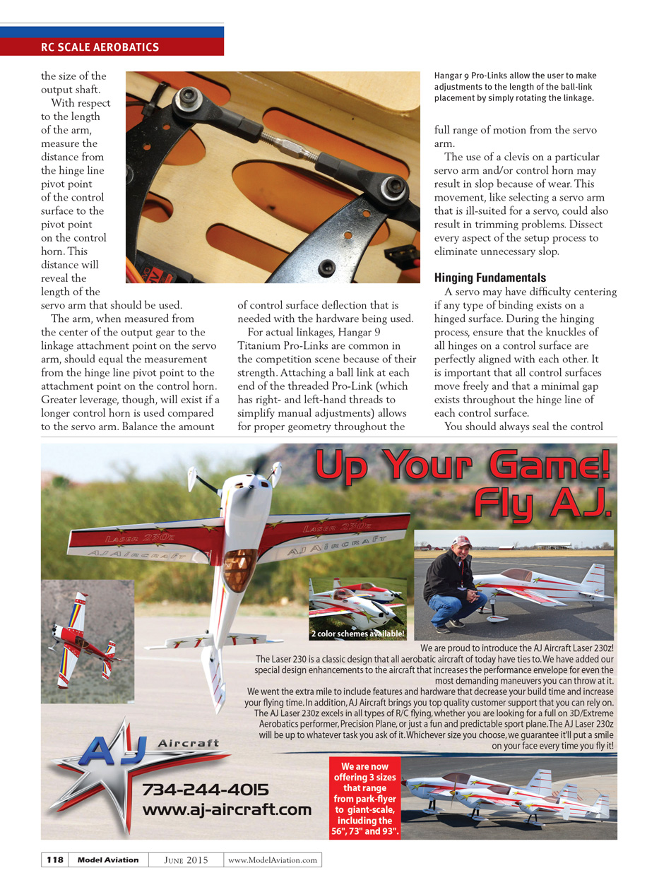
With respect to arm length, measure the distance from the hinge-line pivot point of the control surface to the pivot point on the control horn. The servo arm length, measured from the center of the output gear to the linkage attachment point on the servo arm, should equal the measurement from the hinge-line pivot point to the attachment point on the control horn. Greater leverage will exist if a longer control horn is used compared to the servo arm. Balance the amount of control surface deflection needed with the hardware being used.
For linkages, Hangar 9 Titanium Pro-Links are common in the competition scene because of their strength. Attaching a ball link at each end of the threaded Pro-Link (which has right- and left-hand threads to simplify manual adjustments) allows for proper geometry throughout the full range of motion from the servo arm. The use of a clevis on a particular servo arm and/or control horn may result in slop because of wear. This movement, like selecting an ill-suited servo arm, can result in trimming problems. Dissect every aspect of the setup process to eliminate unnecessary slop.
Hinging Fundamentals
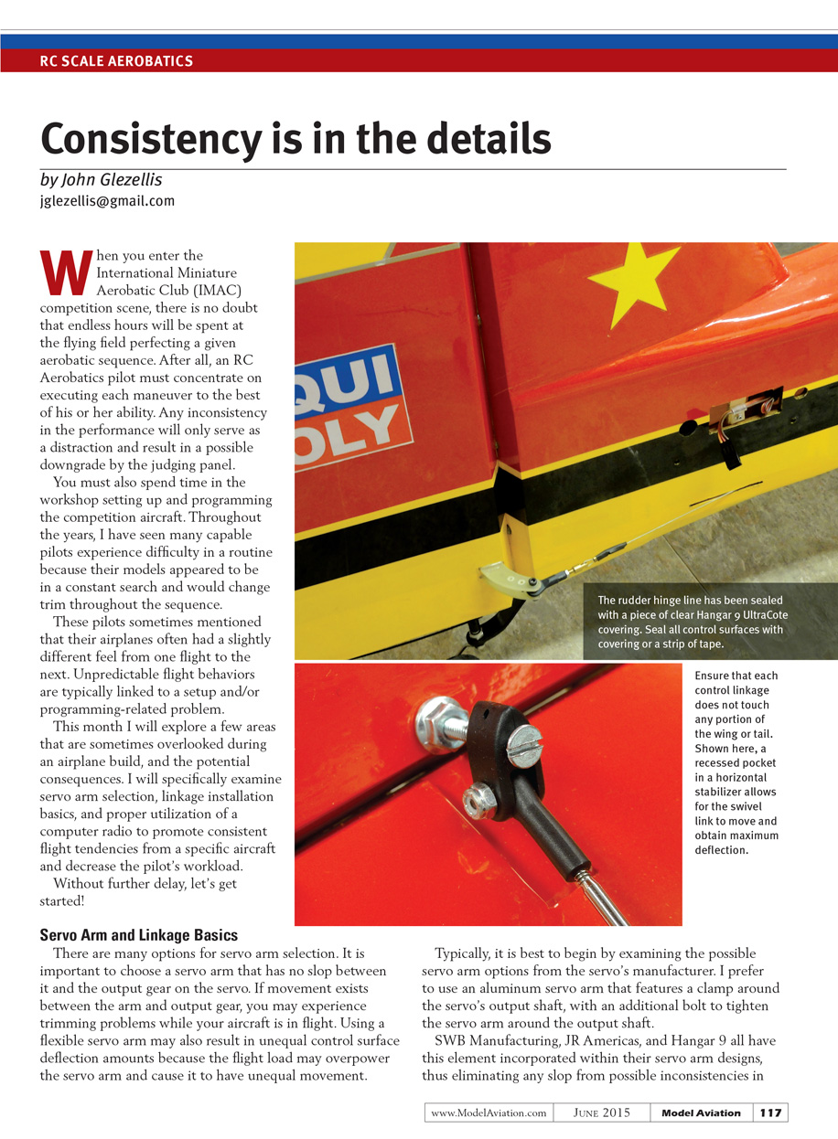
A servo may have difficulty centering if any type of binding exists on a hinged surface. During the hinging process, ensure that the knuckles of all hinges on a control surface are perfectly aligned with each other. It is important that all control surfaces move freely and that a minimal gap exists along the hinge line.
Always seal the hinge line using tape or covering. Sealing the hinge line will help keep dirt and moisture out of the hinge knuckles and minimize the chance of binding.
Travel Adjustment
Radio manufacturers typically refer to the travel adjustment function as either adjustable travel volume (ATV) or end-point adjustment (EPA). This function allows the end user to adjust the total travel of a servo in both directions. Properly using this capability is mandatory.
Many pilots tend to use extremely large servo arms to obtain large amounts of control surface deflection. By doing so, they actually decrease the percentages found within the ATV or EPA function so a specific servo will not bind and move the control surface beyond its physical limitations. This practice is not the proper way to use the function. A servo has the best resolution, torque, and response when ATV/EPA values are maximized.
Always begin by maximizing the travel adjustment percentages for all control surfaces, then adjust the distance of the linkage to the fastening point on the servo arm so the control surface will not move beyond its physical limitation. The goal is to move a given stick on the transmitter to the full amount, having the servo move freely until maximum deflection is obtained.
If the servo cannot move to the full range of motion and binds at the hinge line, do not decrease the ATV or EPA. Instead, move the clevis (or ball link) inward on the servo arm. This will result in a bind-free setup, improved resolution, and more torque from the servo.
Final Thoughts
You have now learned about some of the setup fundamentals required for a properly tuned competition airframe. Always dedicate time both in the shop and at the field to evaluate an aircraft.
Attend an aerobatics competition or a judging seminar to learn more about proper setup and flying techniques. The knowledge you can gain from attending both is endless.
Please visit the IMAC website to see if a competition or seminar is close to you. No matter how many years you have been involved in the competition scene, there is always something to learn from others. This is what competition is all about!
Until next time, fly hard!
SOURCES:
- Hangar 9
(877) 504-0233 www.hangar-9.com
- IMAC
- JR Americas
(217) 352-7959 www.jramericas.com
- SWB Manufacturing, Inc.
(262) 675-2848 www.swbmfg.com
Transcribed from original scans by AI. Minor OCR errors may remain.

