
RC Soaring
THE TOPIC for this month is the wing planform. I will describe the effect of different planforms on the flying characteristics of the airplane. The planform affects induced drag and stall characteristics.
Did you ever wonder why some gliders tip-stall often and others never seem to tip-stall?
There are three major design elements that affect stalling tendencies: planform, twist, and airfoil(s). I am not counting surface finish. All elements have to work in harmony with each other. A good airfoil on a bad wing planform or vice versa will cause problems.
There is a common misconception that an untwisted wing flies with all portions of the wing at the same coefficient of lift (CL). In reality, the lift of the wing induces a vertical component on the air around it. The induced velocity is greater near the wingtips.
On an untwisted constant-chord wing, the wingtips are at a lower effective angle of attack than the root of the wing. You could say that the untwisted constant-chord wing has effective washout. Highly tapered planforms, with small tip chords, have effective wash-in.
How does the optimum wing look?
By manipulating analytical aerodynamics equations, it can be shown that the induced drag of a wing is minimized when the lift distribution is elliptical.
Few practical airplanes are built with truly elliptical lift distributions. Other constraints, such as ease of manufacturing and handling characteristics, are usually more important.
There are two problems with the naive elliptical theoretical solution. First, consider that airplanes need to turn. The analytical solution assumes straight flight.
When a long glider wing turns at low speed, the inboard wing travels much slower than the outboard wing. Lift is proportional to the square of the velocity. The airplane must yaw outward; apply outboard aileron or (usually) both to balance the lift forces in the turn.
Yawing outward and applying outboard aileron each increase the local angle of attack of the inner tip, raising its local CL. Then the inner wingtip has the higher CL than the rest of the wing. The elliptical wing planform will tip-stall into the direction of the turn.
The second problem with the naive elliptical planform has to do with Reynolds numbers. Basically, the airfoil on a small chord works less efficiently than the same airfoil on a larger chord. Instead of the lift being proportional to the chord, there is not enough lift at the tips. This also leads to tip stalls.
I believe that some of the WACO designs suffered from this problem. Both problems with the naive elliptical planform lead us to increase the tip chord in more practical planform designs.
A refined glider wing needs to fly efficiently at a wide range of speeds. The design should not overemphasize high- or low-speed flight; a compromise must be reached. By adding washout to a constant-chord wing, the lift distribution can be made elliptical. This would minimize induced drag.
Unfortunately, the lift distribution is only elliptical at one speed. At high speeds, part of the twisted wing lifts downward and part of it lifts upward. The wing would be fighting itself and creating extra drag. If the wing needs to be efficient at high and low speeds, geometric twist is a bad thing.
For an untwisted wing, planform has little effect on drag at low lift coefficients. In this regime, parasitic drag and airfoil profile drag dominate the induced drag. Slope Razors will not show planform differences in the straightaways—only in the turns, when pulling high lift coefficients, will planform differences become apparent.
Characteristics of an ideal glider planform
An ideal glider planform design has a constant CL over roughly the inner 80% of span. The local CL should be reduced near the wingtips, to give some margin against tip stall while turning.
- Reducing the CL by 20–25% at the tips is enough for my taste. It looks like a truncated ellipse.
- You must still choose a wingtip airfoil that does not stall early on smaller chords.
Another desirable characteristic of the ideal wing is to delay the stall to the highest possible CL. This will maximize the ability of the glider to pull on the winch line. The high available CL also contributes to the glider's ability to fly slowly during landing.
As the angle of attack is increased, the part of the wing that first reaches the airfoil's maximum CL will stall. Once one part of the wing stalls, the rest of the wing follows quickly. When the stall does occur, it should not start from the wingtips.
- Stalling first at the root is desirable for trainer airplanes.
- Stalling first in the middle of the wing or simultaneously on the majority of the wing are acceptable for more experienced pilots.
You might think it is bad to design the wing planform so that most of it stalls simultaneously. I have flown several models with this property. When forced to stall, it is no more violent than other planform designs with the same airfoil and wing loading.
Remember that even on conservative planforms, the stall at the root triggers a stall on the rest of the wing.
Something I did notice about the truncated-ellipse wing was that the nose could be raised abnormally high before the stall occurred. You can get away with murder on the pitch control.
The airfoil plays an essential part in stall characteristics, but I am limiting this discussion to planforms because of the limited amount of space.
An overly aggressive planform maintains a constant CL throughout too much of its span. The ellipse was not truncated enough. If the pilot tips just once in a contest, the designer was too aggressive. If the pilot is forced to fly conservatively because he or she is afraid of a tip-stall, again the planform was too aggressive.
I used to ignore thermals below 30 feet with one of my old kit airplanes because it had a vicious stall. Analysis of the planform showed a relatively high CL at the wingtip.
Planform comparisons
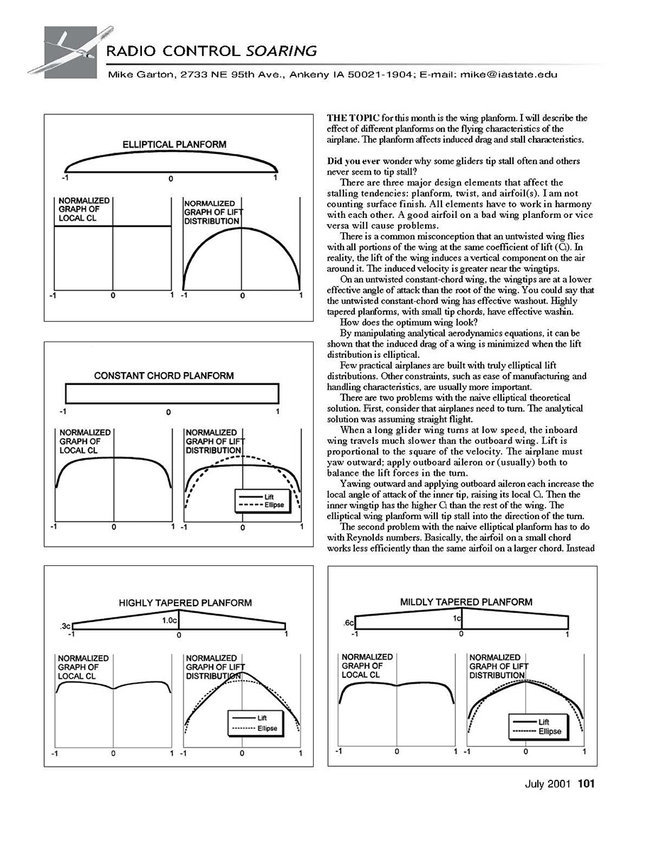
Look at the drawings. First is the naive optimum elliptical planform. The chord distribution is an ellipse. The wing is not twisted. The lift-distribution graph shows a perfect ellipse. The local CL is constant across the entire wing.
If gliders did not need to turn and there were no Reynolds number effects, this would be a good planform.
Second is the constant-chord wing. The lift distribution is far from elliptical. This means it is especially draggy at high lift coefficients. The highest local lift coefficients are at the roots of the wing. It will stall from the root outward. A glider with a constant-chord wing is very easy to fly with no tip-stall tendency.
Next are a couple of straight-taper wings.
- The highly tapered wing with a 0.3 taper ratio has its highest CL near the wingtip. It will tip-stall. Some aerobatic airplanes use highly tapered planforms for better snap-roll performance.
- The mildly tapered wing has its highest CL halfway out. Dodgson Designs and most other aileron gliders of the early 1980s used this type of planform. The handling characteristics are friendly. This planform is easy to manufacture, but fairly draggy at high lift coefficients. A rule of thumb for good-handling straight-tapered wings is to keep the taper ratio above 0.6.
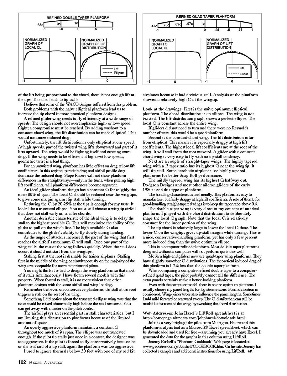
The double-taper wing is very close to my concept of an ideal planform. It plays with the chord distribution to deliberately shape the local CL graph. Note that the local CL is relatively constant for the inner portion of the wing.
- The tip chord is relatively large to lower the local CL there. The lower CL on the wingtips gives tip-stall margin while turning.
- This is a nice, conservative-handling planform, yet has only a few percent more induced drag than the naive optimum ellipse.
- This is a computer-refined planform. Most double-taper planforms designed without a computer will not perform quite this well.
Modern high-end gliders now use quad-taper wing planforms. They have slightly smoother CL distributions. The theoretical induced drag of this planform is 1–2% less than the double-taper planform.
When comparing a computer-refined double taper to a computer-refined quad taper, the pilot probably cannot tell the difference. The extra panels certainly make a better-looking planform.
Even with the computer model, there is no optimum planform. I usually choose my panel lengths for logistics reasons. Foam utilization is considered. Wing-joiner tubes also influence the panel lengths. Sometimes I add mild forward or rearward sweep. The CL distribution can still be made flat for most of the wing, by tweaking the chord distribution.
References and tools
- John Hazel's LiftRoll spreadsheet is at http://homepage.altavista.com/johnhazel/downloads.html. John is a very bright glider pilot from Michigan. He created this planform-analysis tool as a Microsoft Excel spreadsheet, which can be downloaded and used for free—assuming you already have Excel. I generated the data for the graphs in this column using LiftRoll.
- Jeremy Bushnell's "Planform Cookbook" Web page is located at www.geocities.com/jerbushlll/COOKBOOK.htm. On his site, Jeremy has collected examples and additional instructions for using LiftRoll.
MA
Transcribed from original scans by AI. Minor OCR errors may remain.

