
Strong, lightweight fuselage boom repair
By
by Gordon Buckland [email protected]
Overview
Who hasn't dropped a wing on landing or landed out and treed a composite model, snapping the boom? Most mishaps where the model is substantially damaged seem to break the boom generally midway between the wing's trailing edge and the stabilizers. Because this area is far behind the CG, it is important that the repair add as little weight as possible or the model's performance will be compromised and it will require added nose weight to compensate.
The following procedure yields a repair that is adequately strong yet adds less than 3/4 ounce to the model's overall weight.
Materials / tools
- New hypodermic pushrods (.050-inch stainless tubing). Typical size used: .050 x .030 x 60-inch tubing.
- Replacement outer sleeves (if needed).
- Thick CA (Zap thick-viscosity glue) and CA accelerator spray.
- West System G-Flex epoxy (or equivalent).
- Carbon tow (cut into 12 pieces to match grooves).
- Carbon cloth (single wrap to cover joint).
- Masking tape (two layers, at least 1 inch wide on either side of break).
- Electrical or insulation tape.
- Dremel tool with 1/2"–5/8" diameter, 1/8" wide grinding wheel.
- Sandpaper: 360-grit, 600-grit, 1000-grit.
- Sharpie marker.
- Paper towels for blotting excess epoxy.
- Basic hand tools (pliers, cutters, soldering iron if needed), measuring tools, straightedge.
- Work fixtures/boxes to support wing and fuselage during alignment.
Preliminary: pushrod inspection and replacement
- Inspect the stabilizer and rudder pushrods. I typically remove and replace them, because originals are often .050-inch stainless hypodermic tubing and tend to bend during crashes.
- Obtain new hypodermic-tube pushrods (see Sources). Use .050 x .030 x 60-inch tubing.
- Disconnect the clevis at the servo end and either cut or de-solder the clevis end to remove the pushrods from the rear of the fuselage.
- Fold the rudder back against the fin and tape it there. Remove about 1 inch of the balsa rudder post in the back of the fin to gain access to the stabilizer bellcrank.
- Unhitch the clevis and remove the stabilizer pushrod.
- Inspect the outer sleeves and replace them if the new pushrods do not slide freely through when the broken fuselage is aligned. Replacement sleeves are available from CST–The Composites Store.
Repair procedure
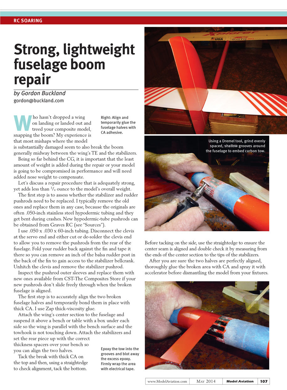
- Accurately align the two broken fuselage halves and temporarily bond them in place with thick CA (Zap thick-viscosity glue).
- Attach the wing's center section to the fuselage and suspend it above a bench or table. Support each side with a box so the wing is parallel with the bench surface and the tow hook is not touching down.
- Attach the stabilizers and set the rear piece up with appropriate thickness spacers over your bench so you can align the two halves precisely.
- Tack the break with thick CA on the top. Using a straightedge to check alignment, tack the bottom. Before tacking the side, use the straightedge to ensure the center seam is aligned. Double-check alignment by measuring from the ends of the center section to the tips of the stabilizers.
- After you are sure the two halves are perfectly aligned, thoroughly glue the broken area with CA and spray with accelerator. Allow to set, then dismantle the model from your fixtures.
- Remove the stabilizers and center section. Carefully use a Dremel tool to grind or sand the area to remove excess or protruding CA from the joint area.
- Tape off the fuselage with two layers of masking tape, at least one inch wide on either side of the break.
- With 360-grit sandpaper, carefully sand the paint from the fuselage between the masking tapes.
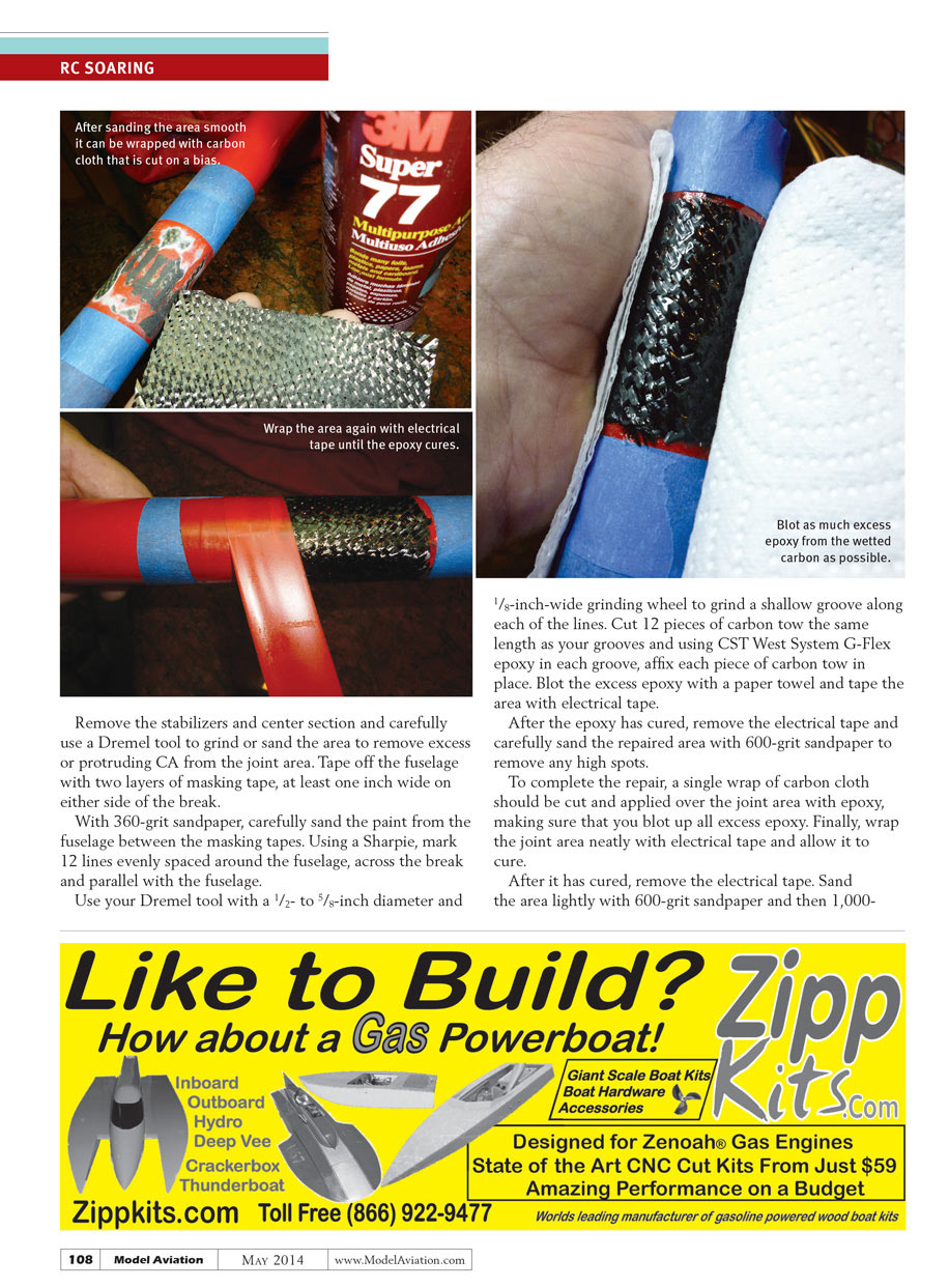
- Using a Sharpie, mark 12 lines evenly spaced around the fuselage, across the break and parallel with the fuselage.
- With the Dremel and the 1/2"–5/8" diameter, 1/8"-wide grinding wheel, grind a shallow groove along each of the 12 lines.
- Cut 12 pieces of carbon tow the same length as your grooves. Using West System G-Flex epoxy, affix each piece of carbon tow in its groove. Blot excess epoxy with a paper towel and tape the area with electrical tape to hold things in place while curing.
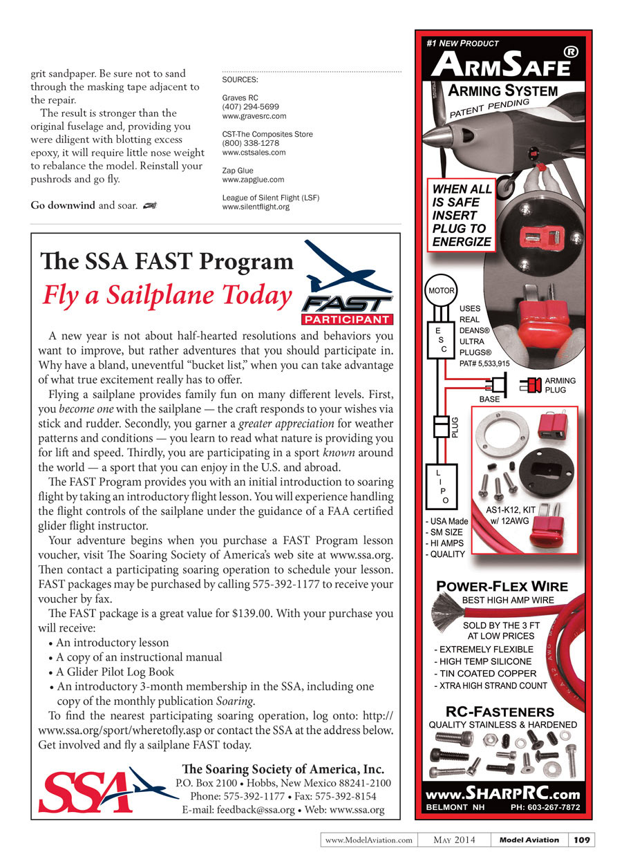
- After the epoxy has cured, remove the electrical tape and carefully sand the repaired area with 600-grit sandpaper to remove any high spots.
- Cut a single wrap of carbon cloth sized to cover the joint area. Apply it over the joint with epoxy, blotting up all excess epoxy.
- Wrap the joint neatly with electrical or insulation tape and allow it to cure.
- After cure, remove the tape and sand the area lightly with 600-grit and then 1000-grit sandpaper. Be careful not to sand through the masking tape adjacent to the repair.
Final steps
- Reinstall the stabilizers, center section, and pushrods. Ensure pushrods slide freely and that control linkages are secure.
- Because you blotted excess epoxy diligently, the repair should add very little weight and may require little or no nose weight to rebalance the model.
- Go downwind and soar.
Notes / tips
- Use a straightedge and measurements to ensure perfect alignment before permanently bonding—the repair strength and flight characteristics depend on accurate alignment.
- Blot excess epoxy frequently; excess resin adds weight.
- Take care when sanding near masking tape to avoid cutting through the surrounding finish.
SOURCES
- Graves RC
(407) 294-5699 www.gravesrc.com
- CST–The Composites Store
(800) 338-1278 www.cstsales.com
- Zap Glue
- League of Silent Flight (LSF)
Transcribed from original scans by AI. Minor OCR errors may remain.

