
RC Soaring
Mike Garton, 2733 NE 95th Ave., Ankeny IA 50021; E-mail: [email protected]
THE THEME of this column is high-performance control systems for gliders.
For starters I'll present experimental data comparing digital servos to analog servos. Next is an introduction to Blaine Rawdon's linkage-analysis spreadsheet. Last I'll introduce the new heavy-duty Rotary Driver System (RDS) components available for large and/or fast models.
All servos compare the current position of the servo pot to the desired position indicated by the signal from the receiver. Analog servos check the difference in positions and power up the motor to adjust it approximately 50 times per second.
Because of the pulsing, a servo under load is moving a little and sliding backward many times per second. Digital servos perform this checking at a frequency roughly six times higher than the analog servos.
Because they pulse more often, digital servos don't slide as far backward. This makes them more accurate and gives additional holding power.
I set out to compare several digital servos to some analog servos under controlled lab conditions. Frank Baldwin set up a fixture and helped me take the data.
I bought a Hitec HS-645MG servo and the HS-5645MG digital servo for a direct analog vs. digital comparison. I tested a JR 341 and the nearly identical Expert SL300.
Added to the mix was a JR DS368 digital servo that uses the same case as the JR 341. The DS368 has metal gears. I also tested the new JR DS3301 servo. Last I threw in an Airtronics 94141 servo as a benchmark.
Each servo was clamped in a machinist vise. A laser pointer was attached to the servo output wheel. Weights were hung off a ball link 0.4 inch from the center of the wheel. Paper was pinned to the ceiling to record deflections with the laser.
For increasing weights, we measured rotation of the servo output wheel on the paper. Centering accuracy was measured with and without load. A regulated power supply kept the input voltage at 4.8 volts.
Average current was measured as a voltage drop across a precision resistor. We observed the waveforms of the servo current pulses on an oscilloscope and noted the peak current.
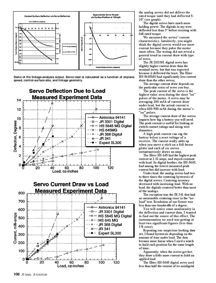
You may be surprised to learn that any force will push a servo away from its center, even if the force is just a fraction of the rated torque. In general, the analog servos did not deliver the rated torque until they had deflected 5-10° (see graph).
The digital servos have much more holding power. The digitals in my tests deflected less than 3° before resisting with full rated torque.
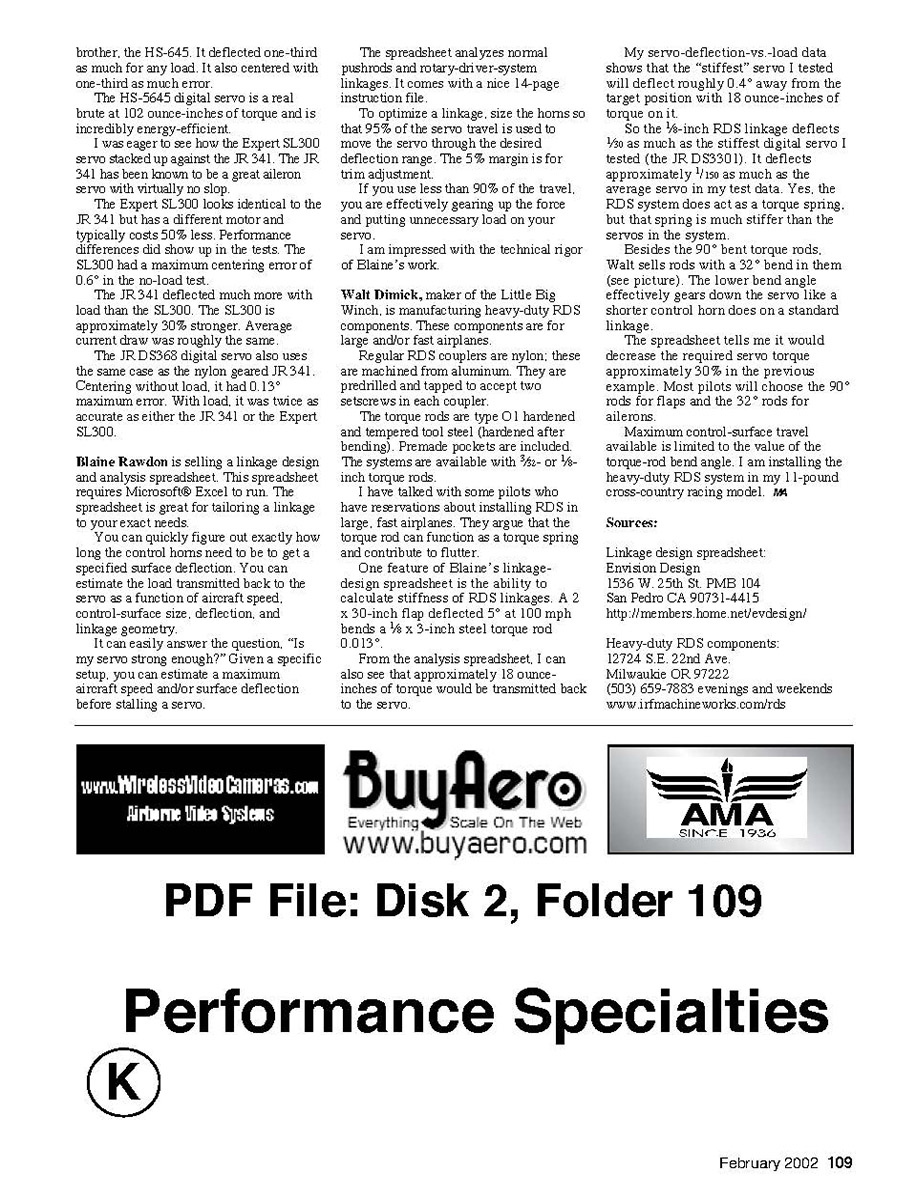
We measured the servos' current characteristics. Intuitively, you might think the digital servos would use more current because they pulse the motor more often. The testing did not reveal a general trend in current draw with type of servo.
The JR DS3301 digital servo has slightly higher current draw than the nominal servo, but that was expected because it deflected the least. The Hitec HS-5645MG had significantly less current draw than the other servos.
The average current draw depends on the particular series of servo you buy.
The peak current of the servo is the highest value seen during the short "on" pulses of the motor. A servo may be averaging 200 mAh of current draw under load, but the actual current is often 600-900 mAh during the motor's "on" pulses.
The average current draw of the servos impacts how big a battery you will need. The peak current is useful for looking at switch contact ratings and sizing wire diameters.
A high peak current can sag the battery below a reset voltage of a receiver. The current really adds up when you move a stick on a full-house glider and each of six servos instantaneously draws an amp.
The Hitec HS-645 had the highest peak current at 1.32 amps, and stayed constant with load. Its digital brother, the HS-5645, had among the lowest measured peak current but did increase with load.
Under load, the analog servos had two to three times the centering hysteresis of the digital servos. Centering accuracy decreased with increasing load. With no load, the digitals centered better than most of the analogs.
The exception was the JR 341 that had no measurable centering error in the "no-load" test. Resolution of our fixture was less than one-hundredth of a degree.
You will notice some nonlinearity in the deflection and current data. I wanted to find out the source of the effect. The instrumentation we used was getting at least two significant figures (less than 1% error).
Repeating one suspicious-looking data set, I found hysteresis depending on the amount of time under load. The data became more linear when I used a watch to hold each position for the same length of time.
Apparently, when the servos get hot, they draw a little more current to hold an applied load.
The Hitec HS-5645 digital servo used less than half the current of its nondigital brother, the HS-645. It deflected one-third as much for any load. It also centered with one-third as much error.
The HS-5645 digital servo is a real brute at 102 ounce-inches of torque and is incredibly energy-efficient.
I was eager to see how the Expert SL300 servo stacked up against the JR 341. The JR 341 has been known to be a great aileron servo with virtually no load.
The Expert SL300 looks identical to the JR 341 but has a different motor and typically costs 50% less. Performance differences did show up in the tests. The SL300 had a maximum centering error of 0.6° in the no-load test.
The JR 341 deflected much more with load than the SL300. The SL300 is approximately 30% stronger. Average current draw was roughly the same.
The JR DS368 digital servo also uses the same case as the nylon geared JR 341. Centering without load, it had 0.13° maximum error. With load, it was twice as accurate as either the JR 341 or the Expert SL300.
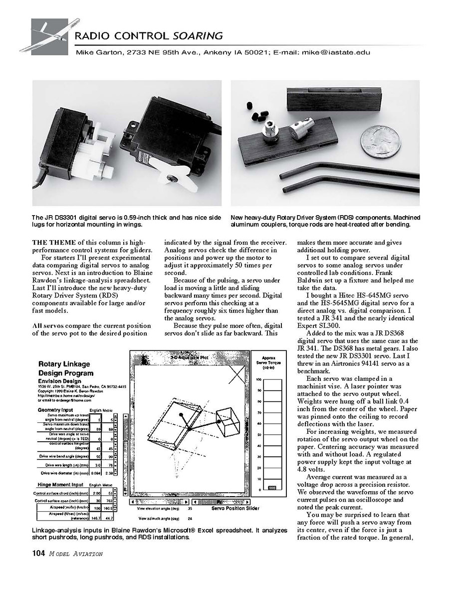
Blaine Rawdon is selling a linkage design and analysis spreadsheet. This spreadsheet requires Microsoft® Excel to run. The spreadsheet is great for tailoring a linkage to your exact needs.
You can quickly figure out exactly how long the control horns need to be to get a specified surface deflection. You can estimate the load transmitted back to the servo as a function of aircraft speed, control-surface size, deflection, and linkage geometry.
It can easily answer the question, "Is my servo strong enough?" Given a specific setup, you can estimate a maximum aircraft speed and/or surface deflection before stalling a servo.
The spreadsheet analyzes normal pushrods and rotary-driver-system linkages. It comes with a nice 14-page instruction file.
To optimize a linkage, size the horns so that 95% of the servo travel is used to move the servo through the desired deflection range. The 5% margin is for trim adjustment.
If you use less than 90% of the travel, you are effectively gearing up the force and putting unnecessary load on your servo.
I am impressed with the technical rigor of Blaine's work.
Walt Dimick, maker of the Little Big Winch, is manufacturing heavy-duty RDS components. These components are for large and/or fast airplanes.
Regular RDS couplers are nylon; these are machined from aluminum. They are predrilled and tapped to accept two set screws in each coupler.
The torque rods are type O1 hardened and tempered tool steel (hardened after bending). Premade pockets are included. The systems are available with 3/32- or 1/8-inch torque rods.
I have talked with some pilots who have reservations about installing RDS in large, fast airplanes. They argue that the torque rod can function as a torque spring and contribute to flutter.
One feature of Blaine's linkage-design spreadsheet is the ability to calculate stiffness of RDS linkages. A 30-inch flap deflected 5° at 100 mph bends a 1/8 x 3-inch steel torque rod 0.013°.
From the analysis spreadsheet, I can also see that approximately 18 ounce-inches of torque would be transmitted back to the servo.
My servo-deflection-vs.-load data shows that the "stiffest" servo I tested will deflect roughly 0.4° away from the target position with 18 ounce-inches of torque on it.
So the 1/8-inch RDS linkage deflects 1/30 as much as the stiffest digital servo I tested (the JR DS3301). It deflects approximately 1/150 as much as the average servo in my test data. Yes, the RDS system does act as a torque spring, but that spring is much stiffer than the servos in the system.
Besides the 90° bent torque rods, Walt sells rods with a 32° bend in them (see picture). The lower bend angle effectively gears down the servo like a shorter control horn does on a standard linkage.
The spreadsheet tells me it would decrease the required servo torque approximately 30% in the previous example. Most pilots will choose the 90° rods for flaps and the 32° rods for ailerons.
Maximum control-surface travel available is limited to the value of the torque-rod bend angle. I am installing the heavy-duty RDS system in my 11-pound cross-country racing model. JH
Sources:
Linkage design spreadsheet: Envision Design 1536 W. 25th St. PMB 104 San Pedro CA 90731-4415 http://members.home.net/envision/
Heavy-duty RDS components: 12724 S.E. 22nd Ave. Milwaukie OR 97222 (503) 659-7883 evenings and weekends www.ifmachineworks.com/rds
Transcribed from original scans by AI. Minor OCR errors may remain.

