
RC Soaring
Mike Garton, 506 NE 6th St., Ankeny IA 50021; E-mail: <REDACTED>
FIBERGLASS FUSELAGES are now standard on high-performance Radio Control (RC) gliders. Installing radio gear in a fiberglass fuselage is different from installing gear in a boxy wooden trainer.
Unfortunately, many of the high-performance gliders do not come with instructions; the manufacturer assumes that the builder already knows how to install his/her gear. If the builder doesn't have experienced flying buddies, there can be quite a knowledge gap.
In this column, I'll explain some techniques for installing gear in a fiberglass fuselage.
These fuselages are made by first shaping a "positive plug" of the desired shape. The designer has the freedom to use round cross-sections and sleek lines. Then a two-piece "negative" mold is created from the plug.
Wet the fiberglass cloth with epoxy, and lay it up in the mold halves. Trim it after it has cured some.
Finally, join the halves with epoxy and a strip of fiberglass cloth.
Molded fiberglass fuselages generally have higher strength-to-weight ratios than wooden fuselages. The fiberglass's fabric weight, weave, and layers can be tailored to particular strength requirements at each spot in the fuselage.
A couple of Web sites have nice photos that show this process. See the addresses at the end of the column.
Adjustable Towhook
My first tip for installing gear in a fiberglass fuselage is how to make a simple adjustable towhook. I learned of this method from Ed Siegers.
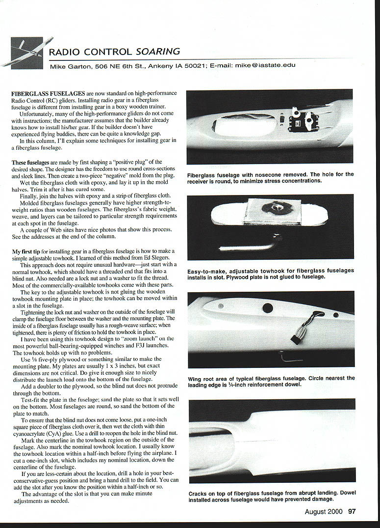
This approach does not require unusual hardware—just start with a normal towhook, which should have a threaded end that fits into a blind nut. Also needed are a lock nut and a washer to fit the thread. Most commercially available towhooks come with these parts.
The key to the adjustable towhook is not gluing the wooden towhook mounting plate in place; the towhook can be moved within a slot in the fuselage.
Tightening the lock nut and washer on the outside of the fuselage will clamp the fuselage floor between the washer and the mounting plate. The inside of a fiberglass fuselage usually has a rough-weave surface; when tightened, there is plenty of friction to hold the towhook in place.
I have been using this towhook design to "zoom launch" on the most powerful ball-bearing-equipped winches and F3J launches. The towhook holds up with no problems.
- Use 1/8-inch plywood or something similar to make the mounting plate. My plates are usually 1 x 3 inches, but exact dimensions are not critical. Do give it enough size to nicely distribute the launch load onto the bottom of the fuselage.
- Add a doubler to the plywood, so the blind nut does not protrude through the bottom.
- Test-fit the plate in the fuselage; sand the plate so that it seats well on the bottom. Most fuselages are round, so sand the bottom of the plate to match.
- To ensure that the blind nut does not come loose, put a one-inch square piece of fiberglass cloth over it, then wet the cloth with thin cyanoacrylate (CyA) glue. Use a drill to reopen the hole in the blind nut.
Mark the centerline in the towhook region on the outside of the fuselage. Also mark the nominal towhook location. I usually know the towhook location within a half-inch before flying the airplane. I cut a one-inch slot, which includes my nominal location, down the centerline of the fuselage.
If you are less certain about the location, drill a hole in your best conservative-guess position and bring a hand drill to the field. You can add the slot after you know the position within a half-inch or so.
The advantage of the slot is that you can make minute adjustments as needed.
Reinforcing the Wing-Load Area (Dowel Crossbrace)
Most Thermal Duration gliders have two-piece wings, joined with a wing rod. The wing rod carries the wing load through the fuselage.
If the nose of your glider digs in on a landing, the wing rod allows the inertia of the wings to bend the wings forward. This compresses the fuselage between the leading edges of the wings.
If you have not properly reinforced the area, the fuselage will crack. It does not take a crash for this problem to show up; moderately fast landings that catch a lump of grass can cause it.
The fix is easy. Install a hardwood dowel or other strong crossbrace in the fuselage between the leading edges. A 1/4- or 5/16-inch dowel works well for two- to three-meter gliders.
To install the dowel, it is easiest to drill through the fuselage from the outside. The holes should be in the wing fairing area, near the leading edge.
- Mark the hole location on the outside of the left and right sides, then drill the holes separately.
- Insert a dowel and mark the required length, then pull the dowel out and trim it to length.
- Add some epoxy and chopped fiberglass fillets on the inside around the dowel.
This method is much quicker and easier than trying to fit a dowel inside without drilling holes.
Most kits don't mention this tip, but don't assume the airplane doesn't need it.
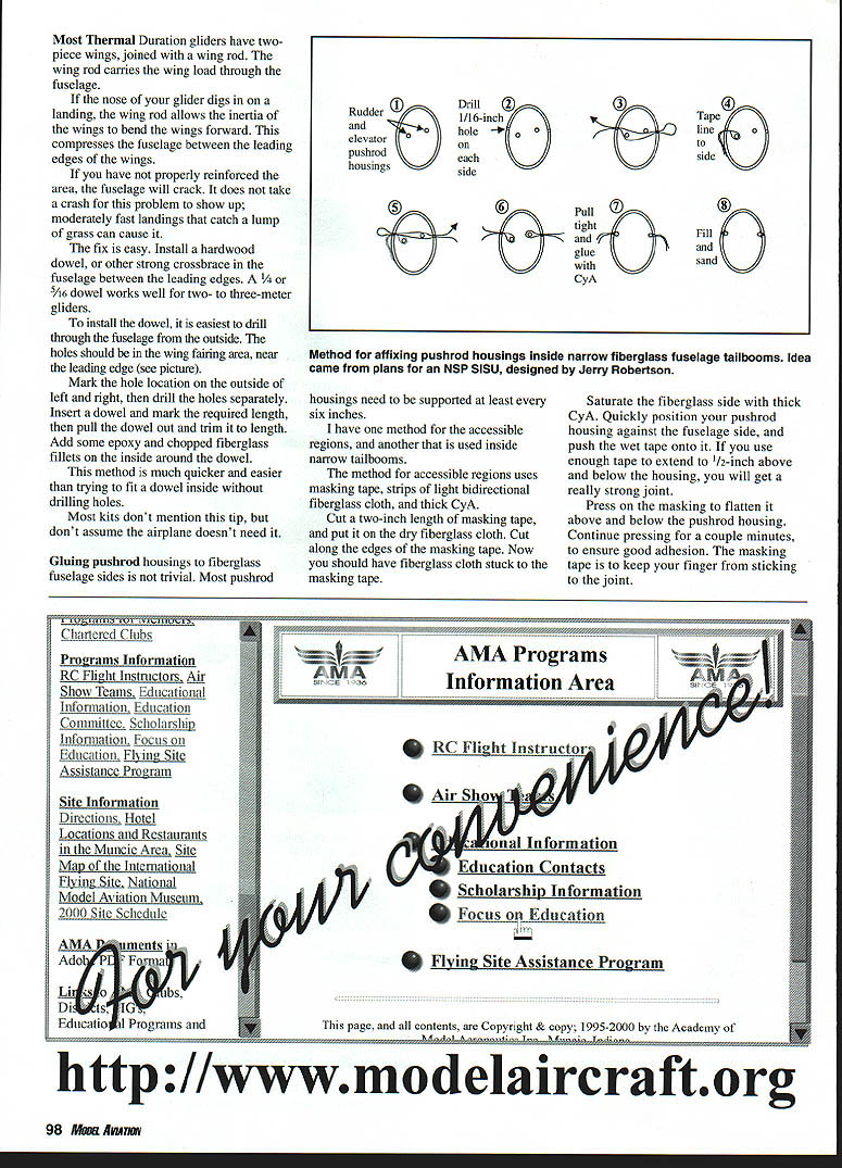
Affixing Pushrod Housings Inside Narrow Fiberglass Tailbooms
Idea came from plans for an NSP SISU, designed by Jerry Robertson.
Pushrod housings need to be supported at least every six inches.
I have one method for the accessible regions, and another that is used inside narrow tailbooms.
Method for accessible regions:
- Use masking tape, strips of light bidirectional fiberglass cloth, and thick CyA.
- Cut a two-inch length of masking tape, and put it on the dry fiberglass cloth. Cut along the edges of the masking tape. Now you should have fiberglass cloth stuck to the masking tape.
- Saturate the fiberglass side with thick CyA. Quickly position your pushrod housing against the fuselage side, and push the wet tape onto it. If you use enough tape to extend 1/2-inch above and below the housing, you will get a really strong joint.
- Press on the masking to flatten it above and below the pushrod housing. Continue pressing for a couple minutes, to ensure good adhesion. The masking tape is to keep your finger from sticking to the joint.
The masking-tape method is not practical inside narrow tailbooms. If you support the housing every six inches, most models will need two or three glue joints inside the tailboom.
Method for narrow tailbooms (heavy-thread pull-through):
- It was scary to drill holes in a nice fiberglass fuselage the first time I tried this method, but the alternative is slop in the controls, caused by unsupported pushrods. Slop in the controls is not acceptable if you want your model to fly well.
- The holes need to be very close to the final location of the pushrods. The holes should also form a straight line lengthwise along the fuselage; this ensures that the pushrod housing will be pulled into a straight line.
- Use a large needle or a piece of thin wire to thread the line through the fuselage. You can navigate above or below the pushrods by angling the wire up or down. It may not be apparent at first, but you need both holes—even if you are just installing one pushrod.
- After both threads are in place, pull them tight and put a drop of thin CyA in the hole. Drop a pinch of baking soda and another drop of CyA in the hole.
- Now you can sand the outside of the fuselage back to its original contour. The threads are sanded off, but the baking soda and CyA hold the pushrod in place. After priming the fuselage, it is difficult to find where the 1/16-inch holes were located.
Soaring Web Site of the Month (It has a nice explanation of the fuselage-molding process):
Another Good Molding Site:
Northeast Sailplanes (SISU): 140 Kirby Ln. Williston VT 05495 (802) 658-9482 e-mail: <REDACTED>
Transcribed from original scans by AI. Minor OCR errors may remain.

