
REDUCE EXHAUST NOISE ...while improving performance and appearance
Rodney B. Pharis
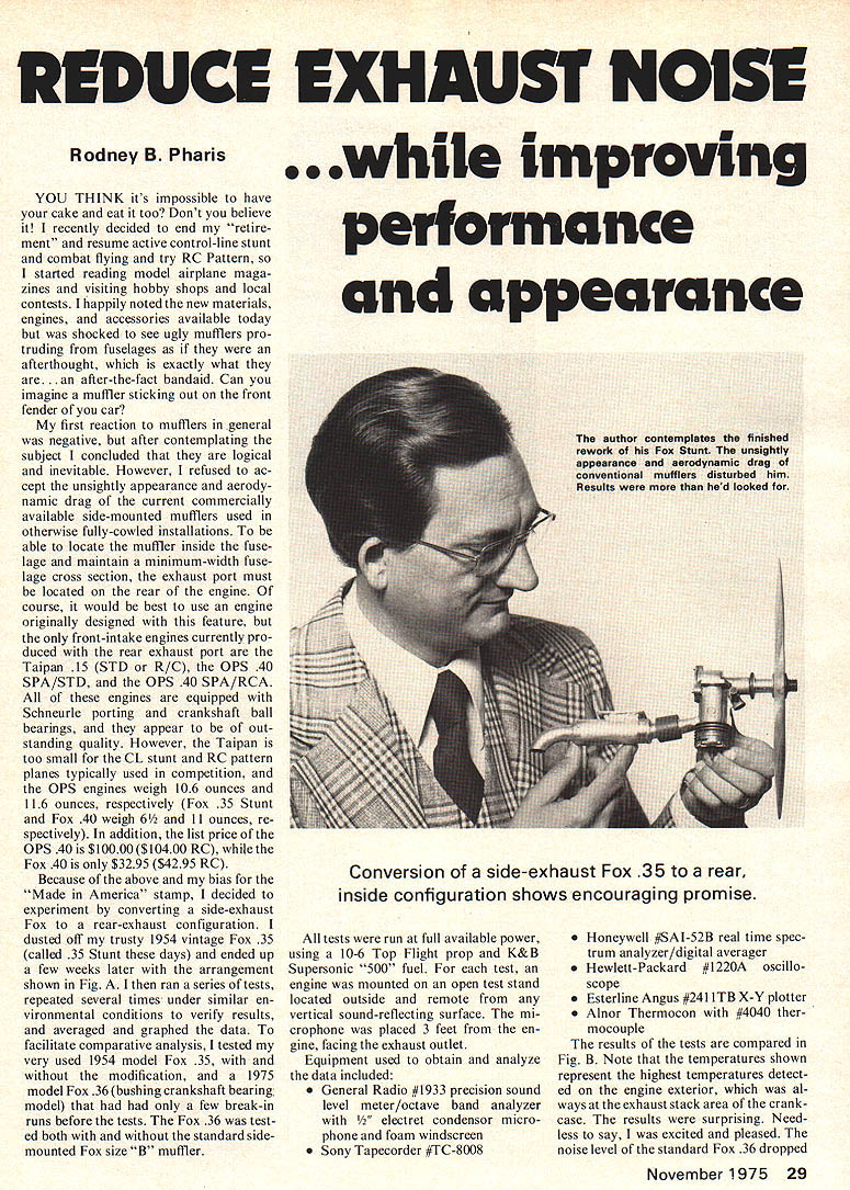
YOU THINK it's impossible to have your cake and eat it too? Don't you believe it! I recently decided to end my "retirement" and resume active control-line stunt and combat flying and try RC Pattern, so I started reading model airplane magazines and visiting hobby shops and local contests. I happily noted the new materials, engines, and accessories available today but was shocked to see ugly mufflers protruding from fuselages as if they were an afterthought, which is exactly what they are...an after-the-fact bandaid. Can you imagine a muffler sticking out on the front fender of your car?
My first reaction to mufflers in general was negative, but after contemplating the subject I concluded that they are logical and inevitable. However, I refused to accept the unsightly appearance and aerodynamic drag of the current commercially available side-mounted mufflers used in otherwise fully-cowled installations. To be able to locate the muffler inside the fuselage and maintain a minimum-width fuselage cross section, the exhaust port must be located on the rear of the engine. Of course, it would be best to use an engine originally designed with this feature, but the only front-intake engines currently produced with the rear exhaust port are the Taipan .15 (STD or R/C), the OPS .40 SPA/STD, and the OPS .40 SPA/RCA. All of these engines are equipped with Schnuerle porting and crankshaft ball bearings, and they appear to be of outstanding quality. However, the Taipan is too small for the CL stunt and RC pattern planes typically used in competition, and the OPS engines weigh 10.6 ounces and 11.6 ounces, respectively (Fox .35 Stunt and Fox .40 weigh 6-1/2 and 11 ounces, respectively). In addition, the list price of the OPS .40 is $100.00 ($104.00 R/C), while the Fox .40 is only $32.95 ($42.95 R/C).
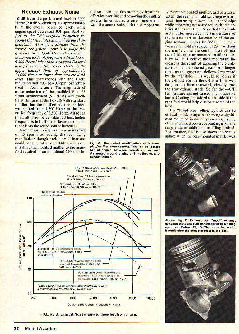
Because of the above and my bias for the "Made in America" stamp, I decided to experiment by converting a side-exhaust Fox to a rear-exhaust configuration. I dusted off my trusty 1954 vintage Fox .35 (called .35 Stunt these days) and ended up a few weeks later with the arrangement shown in Fig. A. I then ran a series of tests, repeated several times under similar environmental conditions to verify results, and averaged and graphed the data. To facilitate comparative analysis, I tested my very used 1954 model Fox .35, with and without the modification, and a 1975 model Fox .36 (bushing crankshaft bearing model) that had had only a few break-in runs before the tests. The Fox .36 was tested both with and without the standard side-mounted Fox size B muffler.
All tests were run at full available power, using a 10-6 Top Flight prop and K&B Supersonic "500" fuel. For each test, an engine was mounted on an open test stand located outside and remote from any vertical sound-reflecting surface. The microphone was placed 3 feet from the engine, facing the exhaust outlet.
Equipment used to obtain and analyze the data included:
- General Radio #1933 precision sound level meter/octave band analyzer with 1/2" electret condenser microphone and foam windscreen
- Sony Tapecorder #TC-8008
- Honeywell #SAI-52B real time spectrum analyzer/digital averager
- Hewlett-Packard #1220A oscilloscope
- Esterline Angus #2411TB X-Y plotter
- Alnor Thermocon #4040 thermocouple
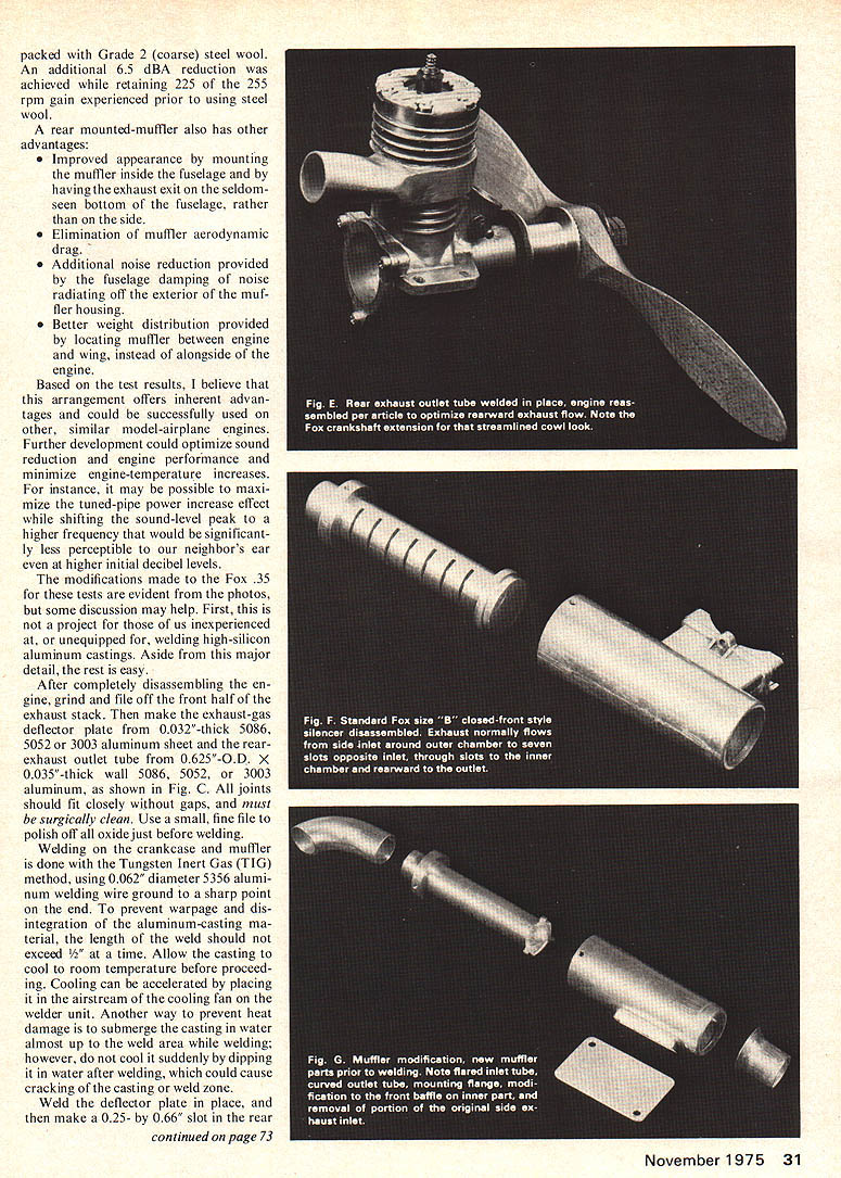
The results of the tests are compared in Fig. B. Note that the temperatures shown represent the highest temperatures detected on the engine exterior, which was always the exhaust stack area of the crankcase. The results were surprising. Needless to say, I was excited and pleased. The noise level of the standard Fox .36 dropped 10 dB peak sound level at 3000 Hertz. dBA refers to A-weighted frequency response which simulates human hearing characteristics at a given distance from the source. The general trend I judge was: frequencies up to 1000 Hertz showed lower measured dB levels; frequencies 1000–6000 Hertz showed higher measured dB levels; frequencies above 6000 Hertz (upper audible limit approximately 14,000 Hertz) showed lower measured dB levels. The lower measured dB level corresponds to a 10-dB reduction — a 300–400 rpm loss. The modified Fox .35 Stunt arrangement measured 92 dBA, essentially the same as the Fox .36 with standard muffler. The muffled peak sound level shifted about 1,500 Hertz to a less-critical frequency near 3,500 Hertz. Although the shift is perceptible at 3 feet, higher frequencies fall off much faster as distance from the sound source increases. Another surprising result was an increase of 15 rpm after adding the rear-facing manifold. Although such a small increase could support a credible conclusion that installing the modified muffler to the manifold resulted in an additional 240-rpm increase. I verified this seemingly irrational effect by inserting and removing the muffler several times during a given engine run, with the same results each time. Apparently the rear-mounted muffler, and to a lesser extent the rear manifold, scavenged exhaust gases, increasing power like a tuned-pipe while improving noise-reduction characteristics at the same time. Note that the standard muffler increased the temperature of the hottest part of the exterior of the engine (exhaust stack) by 85°F. The rear-facing manifold increased it 120°F without the muffler, and the combination of rear manifold and rear-mounted muffler raises it by 140°F. I believe the temperature increase is the result of exposing the crankcase to the hot exhaust gases for a longer time, as the gases are deflected rearward by the manifold. This would not occur if the exhaust port in the cylinder liner was designed to face rearward, directly into the rear exhaust stack. So far the 440°F temperature has not caused any noticeable harm. Cooling fins added to the side of the manifold would help dissipate some of the heat.
The "tuned-pipe" efficiency also can be utilized to advantage in achieving a significant reduction in noise by trading off some of the increased power, depending upon the magnitude of additional muffling desired. For instance, Fig. B shows the results gained when the rear-mounted muffler and modified Fox muffler were used. The Fox .35 Stunt with rear manifold and modified Fox muffler measured 105.3 dBA at 9,780 rpm (440°F). When the modified Fox muffler was further packed with steel wool the sound level dropped to 98.8 dBA at 9,750 rpm (455°F). Packed with Grade 2 (coarse) steel wool. An additional 6.5 dBA reduction was achieved while retaining 225 of the 255 rpm gain experienced prior to using steel wool.
A rear-mounted muffler also has other advantages:
- Improved appearance by mounting the muffler inside the fuselage and by having the exhaust exit on the seldom-seen bottom of the fuselage, rather than on the side.
- Elimination of muffler aerodynamic drag.
- Additional noise reduction provided by the fuselage damping of noise radiating off the exterior of the muffler housing.
- Better weight distribution provided by locating muffler between engine and wing, instead of alongside of the engine.
Based on the test results, I believe that this arrangement offers inherent advantages and could be successfully used on other, similar model-airplane engines. Further development could optimize sound reduction and engine performance and minimize engine-temperature increases. For instance, it may be possible to maximize the tuned-pipe power increase effect while shifting the sound-level peak to a higher frequency that would be significantly less perceptible to our neighbor's ear even at higher initial decibel levels.
The modifications made to the Fox .35 for these tests are evident from the photos, but some discussion may help. First, this is not a project for those of us inexperienced at, or unequipped for, welding high-silicon aluminum castings. Aside from this major detail, the rest is easy.
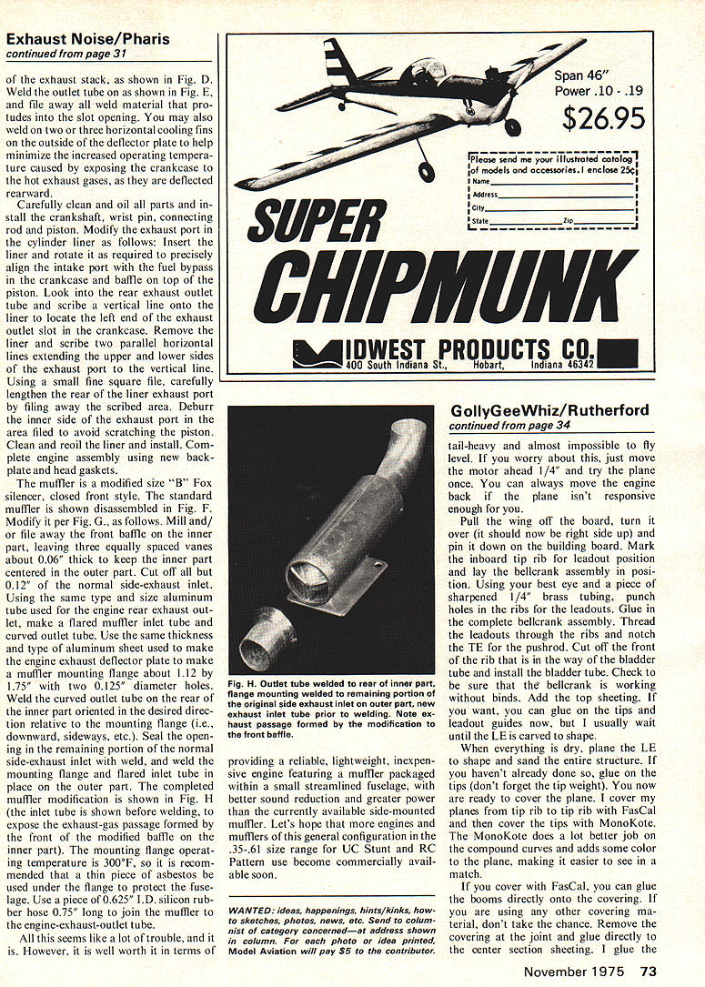
After completely disassembling the engine, grind and file off the front half of the exhaust stack. Then make the exhaust-gas deflector plate from 0.032"-thick 5086, 5052, or 3003 aluminum sheet and the rear-exhaust outlet tube from 0.625"-O.D. x 0.035"-thick wall 5086, 5052, or 3003 aluminum, as shown in Fig. C. All joints should fit closely without gaps, and must be surgically clean. Use a small, fine file to polish off all oxide just before welding.
Welding on the crankcase and muffler is done with the Tungsten Inert Gas (TIG) method, using 0.062" diameter 5356 aluminum welding wire ground to a sharp point on the end. To prevent warpage and disintegration of the aluminum-casting material, the length of the weld should not exceed 3/4" at a time. Allow the casting to cool to room temperature before proceeding. Cooling can be accelerated by placing it in the airstream of the cooling fan on the welder unit. Another way to prevent heat damage is to submerge the casting in water almost up to the weld area while welding; however, do not cool it suddenly by dipping it in water after welding, which could cause cracking of the casting or weld zone.
Weld the deflector plate in place, and then make a 0.25- by 0.66" slot in the rear of the exhaust stack, as shown in Fig. D. Weld the outlet tube on as shown in Fig. E, and file away all weld material that protrudes into the slot opening. You may also weld on two or three horizontal cooling fins on the outside of the deflector plate to help minimize the increased operating temperature caused by exposing the crankcase to the hot exhaust gases, as they are deflected rearward.
Carefully clean and oil all parts and install the crankshaft, wrist pin, connecting rod and piston. Modify the exhaust port in the cylinder liner as follows: Insert the liner and rotate it as required to precisely align the intake port with the fuel bypass in the crankcase and baffle on top of the piston. Look into the rear exhaust outlet tube and scribe a vertical line onto the liner to locate the left end of the exhaust outlet slot in the crankcase. Remove the liner and scribe two parallel horizontal lines extending the upper and lower sides of the exhaust port to the vertical line. Using a small fine square file, carefully lengthen the rear of the liner exhaust port by filing away the scribed area. Deburr the inner side of the exhaust port in the area filed to avoid scratching the piston. Clean and recoil the liner and install. Complete engine assembly using new backplate and head gaskets.
The muffler is a modified size "B" Fox silencer, closed front style. The standard muffler is shown disassembled in Fig. F. Modify it per Fig. G, as follows. Mill and/or file away the front baffle on the inner part, leaving three equally spaced vanes about 0.06" thick to keep the inner part centered in the outer part. Cut off all but 0.12" of the normal side-exhaust inlet. Using the same type and size aluminum tube used for the engine rear exhaust outlet, make a flared muffler inlet tube and curved outlet tube. Use the same thickness and type of aluminum sheet used to make the engine exhaust deflector plate to make a muffler mounting flange about 1.12 by 1.75" with two 0.125" diameter holes. Weld the curved outlet tube on the rear of the inner part oriented in the desired direction relative to the mounting flange (i.e., downward, sideways, etc.). Seal the opening in the remaining portion of the normal side-exhaust inlet with weld, and weld the mounting flange and flared inlet tube in place on the outer part. The completed muffler modification is shown in Fig. H (the inlet tube is shown before welding, to expose the exhaust-gas passage formed by the front baffle of the inner part). The mounting flange operating temperature is 300°F, so it is recommended that a thin piece of asbestos be used under the flange to protect the fuselage. Use a piece of 0.625" I.D. silicone rubber hose 0.75" long to join the muffler to the engine-exhaust-outlet tube.
All this seems like a lot of trouble, and it is. However, it is well worth it in terms of providing a reliable, lightweight, inexpensive engine featuring a muffler packaged within a small streamlined fuselage, with better sound reduction and greater power than the currently available side-mounted muffler. Let's hope that more engines and mufflers of this general configuration in the .35–.61 size range for UC Stunt and RC Pattern use become commercially available soon.
Transcribed from original scans by AI. Minor OCR errors may remain.

