
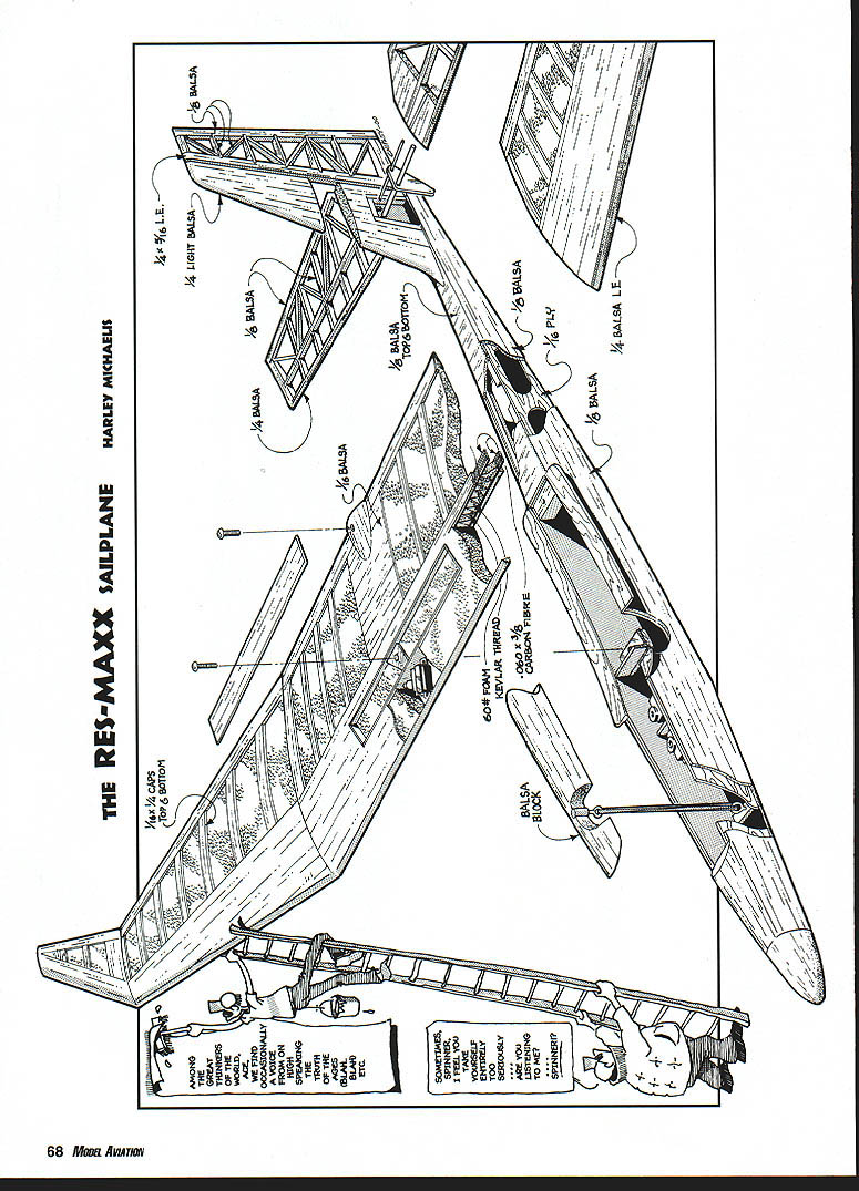
RES-Maxx
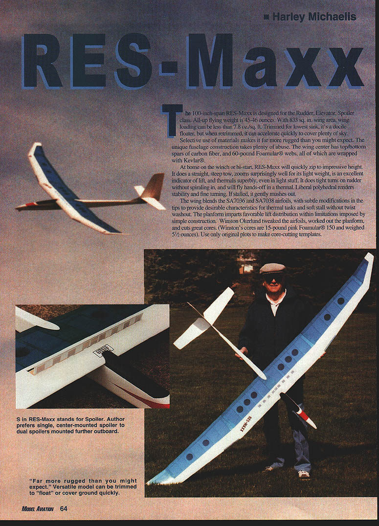
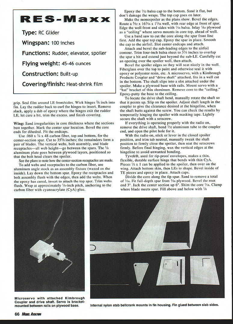
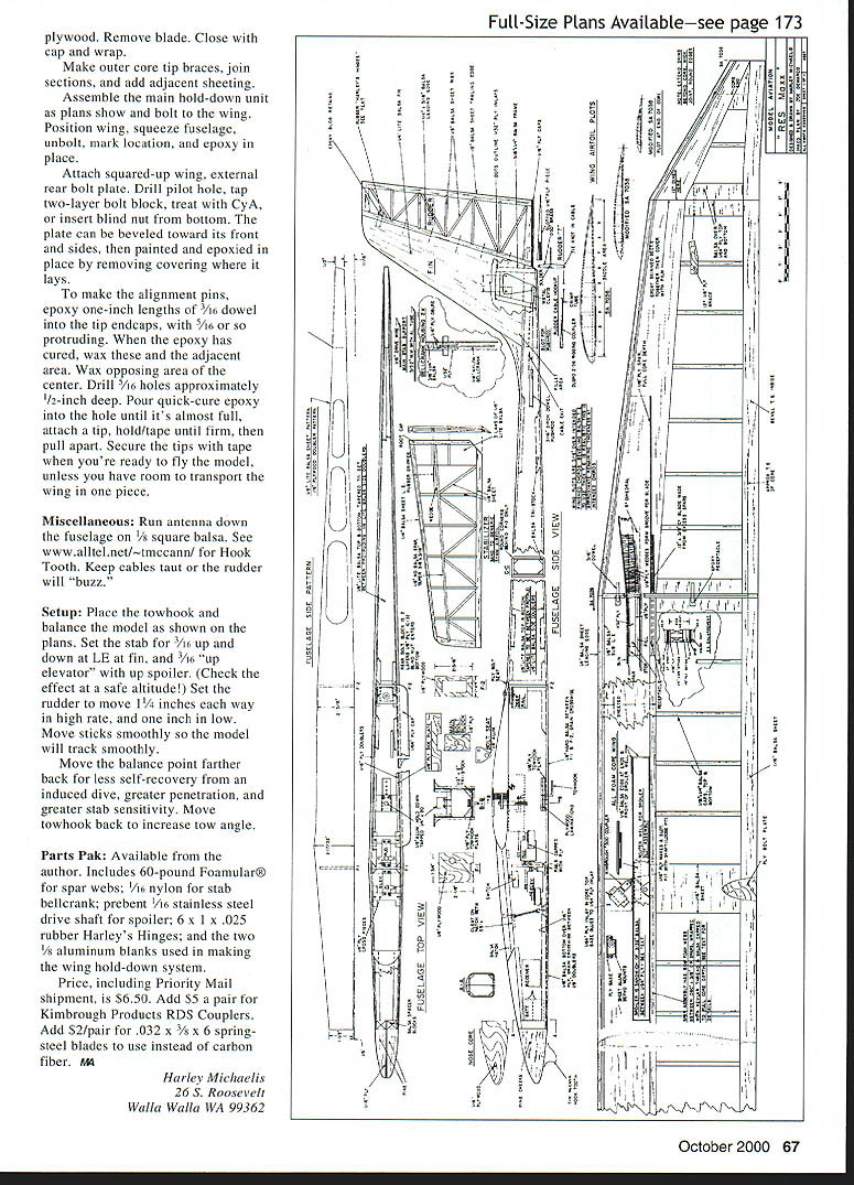
The 100-inch-span RES-Maxx is designed for the Rudder, Elevator, Spoiler class. All-up flying weight is 45–46 ounces. With 833 sq. in. wing area, wing loading can be less than 7.5 oz./sq. ft. Trimmed for lowest sink, it's a docile floater, but when retrimmed it can accelerate quickly to cover plenty of sky.
Selective use of materials makes it far more rugged than you might expect. The unique fuselage construction takes plenty of abuse. The wing center has top and bottom spars of carbon fiber, and 60-pound Foamular® webs, all of which are wrapped with Kevlar®.
At home on the winch or hi-start, RES-Maxx will quickly zip to impressive heights; it does a straight, steep tow, zooms surprisingly well for its light weight, is an excellent indicator of lift, and thermals superbly, even in light stuff. It does tight turns on rudder without spiraling in, and will fly hands-off in a thermal. Liberal polyhedral renders stability and fine turning. If stalled, it gently mushes out.
The wing blends the SA7036 and SA7038 airfoils, with subtle modifications in the tips to provide desirable characteristics for thermal tasks and a soft stall without twist washout. The planform imparts favorable lift distribution within limitations imposed by simple construction. Winston Okerlund tweaked the airfoils, worked out the planform, and cuts great cores. Winston's cores are 15-pound pink Foamular® 150 and weighed 5½ ounces. Use only original plots to make core-cutting templates.
A 36-inch flat center and 32-inch tips make for easy transport. In the center, balsa extends forward from the spar for D-box-like construction. Caps are applied behind as "ribs." Holes between bays provide a see-through, nostalgic effect with transparent films. Ready to fly, the wing weighs less than 22 ounces.
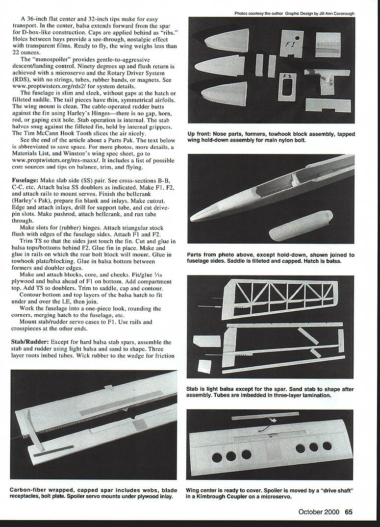
The "monospoiler" provides gentle-to-aggressive descent/landing control. Ninety degrees up and flush return is achieved with a microservo and the Rotary Driver System (RDS), with no strings, tubes, rubber bands, or magnets. See www.proptwisters.org/rds2/ for system details.
The fuselage is slim and sleek, without gaps at the hatch or filleted saddle. The tail pieces have thin, symmetrical airfoils. The wing mount is clean. The cable-operated rudder butts against the fin using Harley's Hinges—there is no gap, horn, rod, or gaping exit hole. Stab operation is internal. The stab halves snug against the filleted fin, held by internal grippers.
The Tim McCann Hook Tool slices the air nicely.
See the end of the article about a Parts Pak. The text below is abbreviated to save space. For more photos, more details, a Materials List, and Winston's wing spec sheet, go to www.proptwisters.org/res-maxx/. It includes a list of possible core sources and tips on balance, trim, and flying.
Fuselage
- Make slab side (SS) pair. See cross-sections B-B, C-C, etc.
- Attach balsa SS doublers as indicated.
- Make F1, F2, and attach rails to mount servos.
- Finish the bellcrank (Harley's Pak), prepare in blank and inlays.
- Make cutout. Edge and attach inlays, drill for support tube, and cut driven slots.
- Make pushrod, attach bellcrank, and run tube through.
Make slots for (rubber) hinges. Attach triangular stock flush with edges of the fuselage sides. Attach F1 and F2. Trim TS so that the sides just touch the fin. Cut and glue in balsa tops/bottoms behind F2. Glue fin in place. Make and glue in rails on which the rear bolt block will mount. Glue in towhook plate/blocking. Glue in balsa bottom between formers and doubler edges.
Make and attach blocks, core, and cheeks. Fit and glue 1/16 plywood and balsa ahead of F1 on bottom. Add compartment top. Add TS to doublers. Trim to saddle, cap and contour.
Contour bottom and top layers of the balsa hatch to fit under and over the leading edge (LE), then join.
Work the fuselage into a one-piece look, rounding the corners, merging hatch to the fuselage, etc.
Mount stab/rudder servo cases to F1. Use rails and crosspieces at the other ends.
Stab / Rudder
Except for hard balsa stab spars, assemble the stab and rudder using light balsa and sand to shape. Three-layer roots embed tubes. Wick rubber to the wedge for friction.
Wing
- Sand irregularities in core thickness where the sections butt together.
- Mark the center spar location. Bevel the core ends for dihedral. Fit the endcaps.
Use .060 x 3/8 x 48 carbon fiber, top and bottom, for the center-section spar. Cut to 35½ inches; the remainders form a pair of blades. The vertical webs, bolt assembly and blade receptacles — all web height — go between the spars. The 1/8 aluminum plate goes between plywood layers, positioned so that the bolt head clears the spoiler.
See the plans to note how the center-section receptacles are made. To add webs and receptacles to the carbon fiber, use aluminum angle stock as an assembly fixture (waxed on the inside). Lay down the bottom spar. Epoxy the receptacles and bolt assembly flush with the edges, then add the webs. When the epoxy has cured, invert to attach the top spar. Trim webs flush. Wrap at approximately 1/4-inch pitch, anchoring to the carbon fiber with cyanoacrylate (CyA) glue.
Epoxy the 1/32 balsa cap to the bottom. Sand it flat, but don’t damage the wraps. The top cap goes on later.
Make the monospoiler as the plans show. Bevel the edges. Route a 3/32 x 16 3/16 x 1/16 well, with rear edge at front of spar. Edge the well front and sides with 1/16 balsa. Inlay 1/64 plywood as a “ceiling” where servo mounts in core top, ahead of the well.
Use a band saw to cut the core along the spar front line first. Add the spar top cap. Epoxy the spar in place. Smooth the cap to the airfoil. Slot center endcaps and attach.
Attach and bevel the sub-leading edges to the airfoil contour. Trim four-inch balsa sheet to 3/4 inches to overlap the spar a bit and extend just beyond the sub-LE. Carefully cut an opening over the spoiler well, then attach.
Bevel the spoiler edges so they will seat nicely in the well. Fiberglass over the top to paint and otherwise seal it with epoxy or polyester resin, etc. A microservo, with a Kimbrough Products Coupler and “drive shaft” attached, fits in a well cut in the bottom. The shaft slips into a slot attached under the spoiler. Make a plywood base with rails. Mount servo with a “hat” bracket of thin aluminum. Remove core to the “ceiling.” Epoxy-putty the base to the ceiling.
To locate the drive shaft bend, manually rotate the shaft so that it points up. Slip on the spoiler. Adjust shaft length in the coupler to give the clearance desired at the hingeline, when the shaft butts against the screw. You can check the results by temporarily hinging the spoiler with masking tape. Lightly secure the shaft with a setscrew.
If everything is operating properly with the radio on, remove the drive shaft, bond 3/32 aluminum tube to the coupler end, and open the pilot hole for it.
With the radio on, stick or lever in the closed spoiler position, and trim tab neutral, manually tweak the shaft position to firmly close the spoiler, then seat the setscrews firmly. Before final hinging, wax the vertical edges at the hingeline to avoid unwanted bonding.
Tyvek®, used for rip-proof envelopes, makes a thin, flexible, durable surface hinge that bonds with thin CyA. Pieces 1/2 x 1 can be applied to the spoiler, then cover on the wing. Attach bottom skin, then LEs to shape. Bevel inside of TE pieces and epoxy in place. Attach caps.
Divide the core along the tip spar. Sand to remove a total of 1/16. Fit full-depth spar from 1/16 plywood. Bevel the root end 3°. Jack the center section up 6°. Shim the core 1/8. Clamp where blade meets spar. Fill above and below with 1/8 plywood. Remove blade. Close with cap and wrap.
Make outer core tip braces, join sections, and add adjacent sheeting.
Assemble the main hold-down unit as plans show and bolt to the wing. Position wing, squeeze fuselage, unbolt, mark location, and epoxy in place.
Attach squared-up wing, external rear bolt plate. Drill pilot hole, tap two-layer bolt block, treat with CyA, or insert blind nut from bottom. The plate can be beveled toward its front and sides, then painted and epoxied in place by removing covering where it lays.
To make the alignment pins, epoxy one-inch lengths of 3/16 dowel into the tip endcaps, with about 5/16 protruding. When the epoxy has cured, wax these and the adjacent area. Wax opposing area of the center. Drill 5/16 holes approximately 1/2-inch deep. Pour quick-cure epoxy into the hole until it's almost full, attach a tip, hold/tape until firm, then pull apart. Secure the tips with tape when you're ready to fly the model, unless you have room to transport the wing in one piece.
Miscellaneous
- Run antenna down the fuselage on 1/8 square balsa. See www.alltel.net/~tmccann/ for Hook Tooth.
- Keep cables taut or the rudder will "buzz."
Setup
- Place the towhook and balance the model as shown on the plans.
- Set the stab for 3/16" up and down at the LE at fin, and 3/16" "up elevator" with up spoiler. (Check the effect at a safe altitude!)
- Set the rudder to move 1 1/4 inches each way in high rate, and one inch in low.
- Move sticks smoothly so the model will track smoothly.
Move the balance point farther back for less self-recovery from an induced dive, greater penetration, and greater stab sensitivity. Move towhook back to increase tow angle.
Parts Pak
Available from the author. Includes:
- 60-pound Foamular® for spar webs
- 1/16 nylon for stab bellcrank
- prebent 1/16 stainless steel drive shaft for spoiler
- 6 x 1 x .025 rubber Harley's Hinges
- the two 3/8 aluminum blanks used in making the wing hold-down system
Price, including Priority Mail shipment, is $6.50. Add $5 a pair for Kimbrough Products RDS Couplers. Add $2/pair for .032 x 3/8 x 6 spring-steel blades to use instead of carbon fiber.
Harley Michaelis <REDACTED>
No additional PRIMARY ARTICLE text appears on this page.
Transcribed from original scans by AI. Minor OCR errors may remain.

