

The Rest of the Crash Story
by Don Apostolico
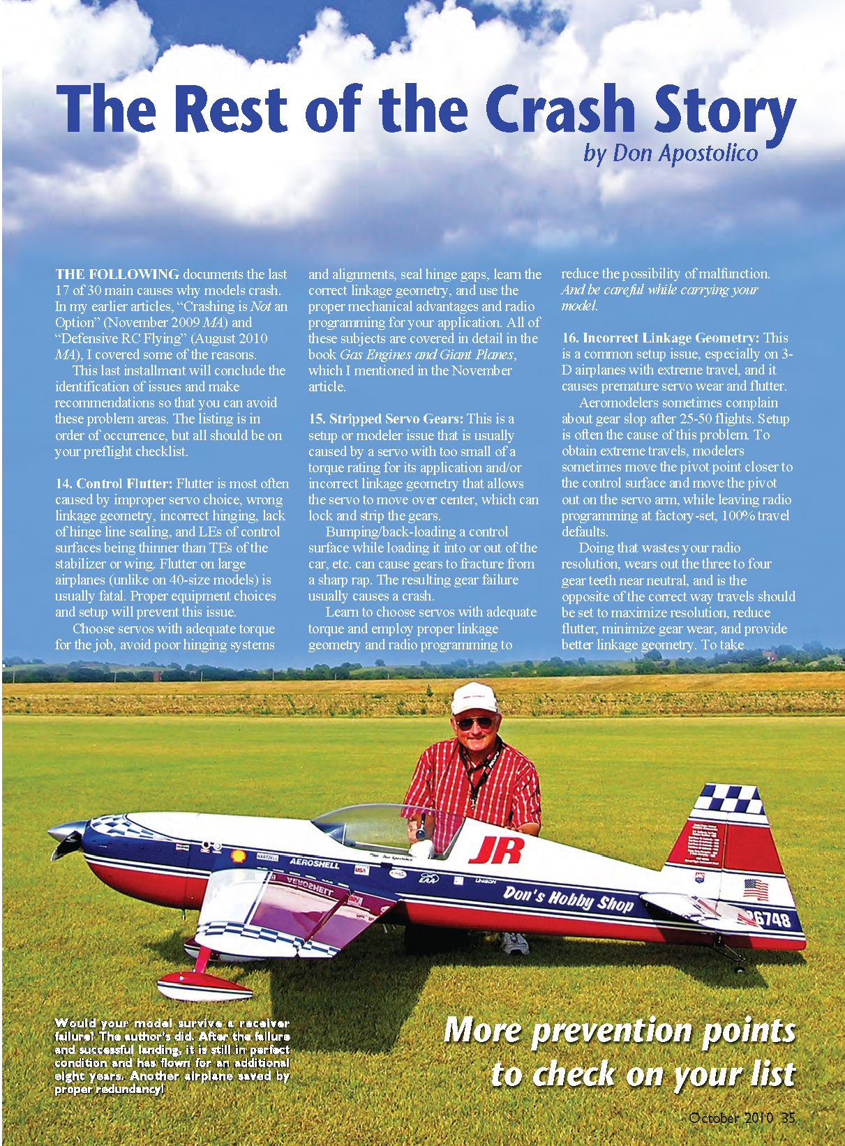
The following documents the last 17 of 30 main causes why models crash. In my earlier articles, “Crashing is Not an Option” (November 2009 MA) and “Defensive RC Flying” (August 2010 MA), I covered some of the reasons.
This last installment will conclude the identification of issues and make recommendations so that you can avoid these problem areas. The listing is in order of occurrence, but all should be on your preflight checklist.
14. Control Flutter
Flutter is most often caused by improper servo choice, wrong linkage geometry, incorrect hinging, lack of hinge-line sealing, and leading edges (LEs) of control surfaces being thinner than trailing edges (TEs) of the stabilizer or wing. Flutter on large airplanes (unlike on .40-size models) is usually fatal. Proper equipment choices and setup will prevent this issue.
Choose servos with adequate torque for the job, avoid poor hinging systems and alignments, seal hinge gaps, learn the correct linkage geometry, and use the proper mechanical advantages and radio programming for your application. All of these subjects are covered in detail in the book Gas Engines and Giant Planes, which I mentioned in the November article.
15. Stripped Servo Gears
This is a setup or modeler issue that is usually caused by a servo with too small a torque rating for its application and/or incorrect linkage geometry that allows the servo to move over center, which can lock and strip the gears.
Bumping or back-loading a control surface while loading it into or out of the car, etc., can cause gears to fracture from a sharp rap. The resulting gear failure usually causes a crash.
Learn to choose servos with adequate torque and employ proper linkage geometry and radio programming to reduce the possibility of malfunction. And be careful while carrying your model.
16. Incorrect Linkage Geometry
This is a common setup issue, especially on 3-D airplanes with extreme travel, and it causes premature servo wear and flutter.
Aeromodelers sometimes complain about gear slop after 25–50 flights. Setup is often the cause of this problem. To obtain extreme travels, modelers sometimes move the pivot point closer to the control surface and move the pivot out on the servo arm, while leaving radio programming at factory-set, 100% travel defaults.
Doing that wastes your radio resolution, wears out the three to four gear teeth near neutral, and is the opposite of the correct way travels should be set to maximize resolution, reduce flutter, minimize gear wear, and provide better linkage geometry. To take advantage of your radio resolution, do the following.
Before connecting any linkage, the travel-adjust feature (Adjustable Travel Volume, or ATV) in your radio endpoint travels should be set to their maximum—usually 140%–150%. One can argue that a slightly lower maximum ATV point, say 5 percentage points below full, will allow for fine-tuning later.
The higher ATV setting forces the pivot-point adjustment to go out on the control surface and in on the servo arm. Doing so provides a more stable leverage arm, a higher tolerance to flutter, better resolution, and reduced gear train wear around neutral, because these settings force the servo to use all of its travel rather than just the few teeth close to neutral.
Doing the opposite (in on the control surface and out on the servo) is conducive to flutter, lower resolution, and gear wear, with the servos often being blamed for having sloppy tolerances. If you are using only a few teeth close to neutral because of improper setup, don’t blame the servo and don’t be surprised if you blow through your servo gears in as few as 25–50 flights.
Ensure that linkage geometry is correct to avoid flutter, sloppy servo centering, and poor resolution.
17. Inadequate Servo Torque for Intended Application
I spoke with an aeromodeler who was setting up a 30-pound model with trainer servos equipped with 40 in-oz of output. He was emphatic that this setup would work because his buddy, who had been flying for years, said that it would.
It was an accident waiting to happen. The torque rating on “standard” servos is inadequate, and the gear train is not robust enough to consistently withstand flight loads on a large airplane. If 40 in-oz servos worked safely on this size of model, we would all be flying the same equipment.
Leave your .40- to .60-size thinking behind when setting up a big model or you might be spending your money on lawyers rather than airplanes. Learn how to determine what servo torque is adequate to handle the flight loads for your application.
18. Radio Frequency Crosstalk on 72 MHz and 2.4 GHz Systems
This can be a setup issue and/or a faulty component that causes deficient range checks, or crosstalk.
Equipment separation is paramount when setting up gas-powered aircraft with a 72 MHz system, and we have learned, through troubleshooting, that 2.4 GHz systems are also affected, but to a lesser degree.
Failure to maintain the recommended distances of radio gear from the ignition system is a typical pilot setup error. Mounting electrical components too close can spread the radio frequency injection into other components and, subsequently, lock out the receiver or reduce your range.
Ensure that receivers, antennas, and other electrical components are at least 3 inches from any other electronic components and at right angles to the ignition system wiring.
19. Improper Tank Plumbing
High-powered engines, gas or glow, operating on medium-size fuel lines, small clunks, or through small brass tubing often run hot, lean out, or seize because they can't be richened. Mounting the internal clunk too close to the back of the tank (within 1/2 inch) will cause fuel-flow issues that can make an engine run lean, sometimes quit, and, in worse cases, seize.
Mounting the vent line so that the top of the tank can close off the vent will cause the engine to run lean, run hot, or seize. Hard-mounting a tank can bring about fuel foaming and cause the same symptoms and erratic operation.
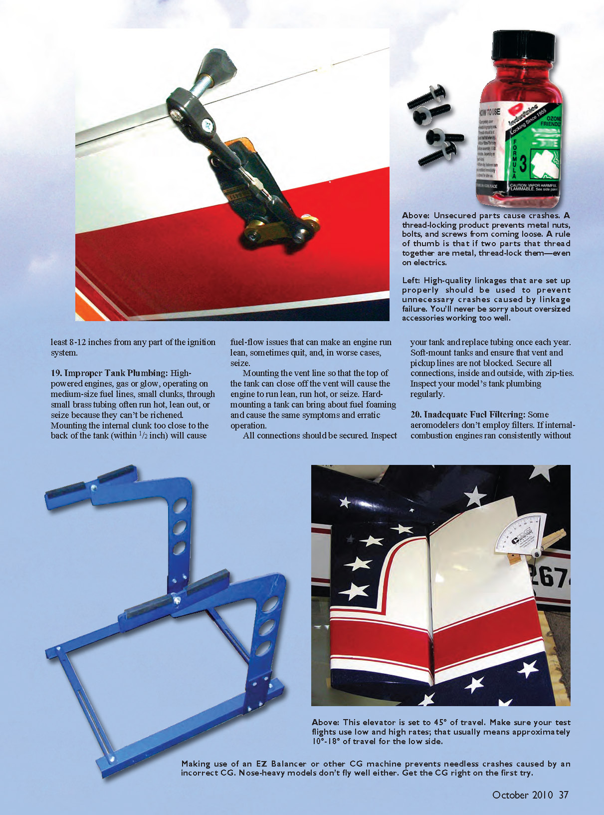
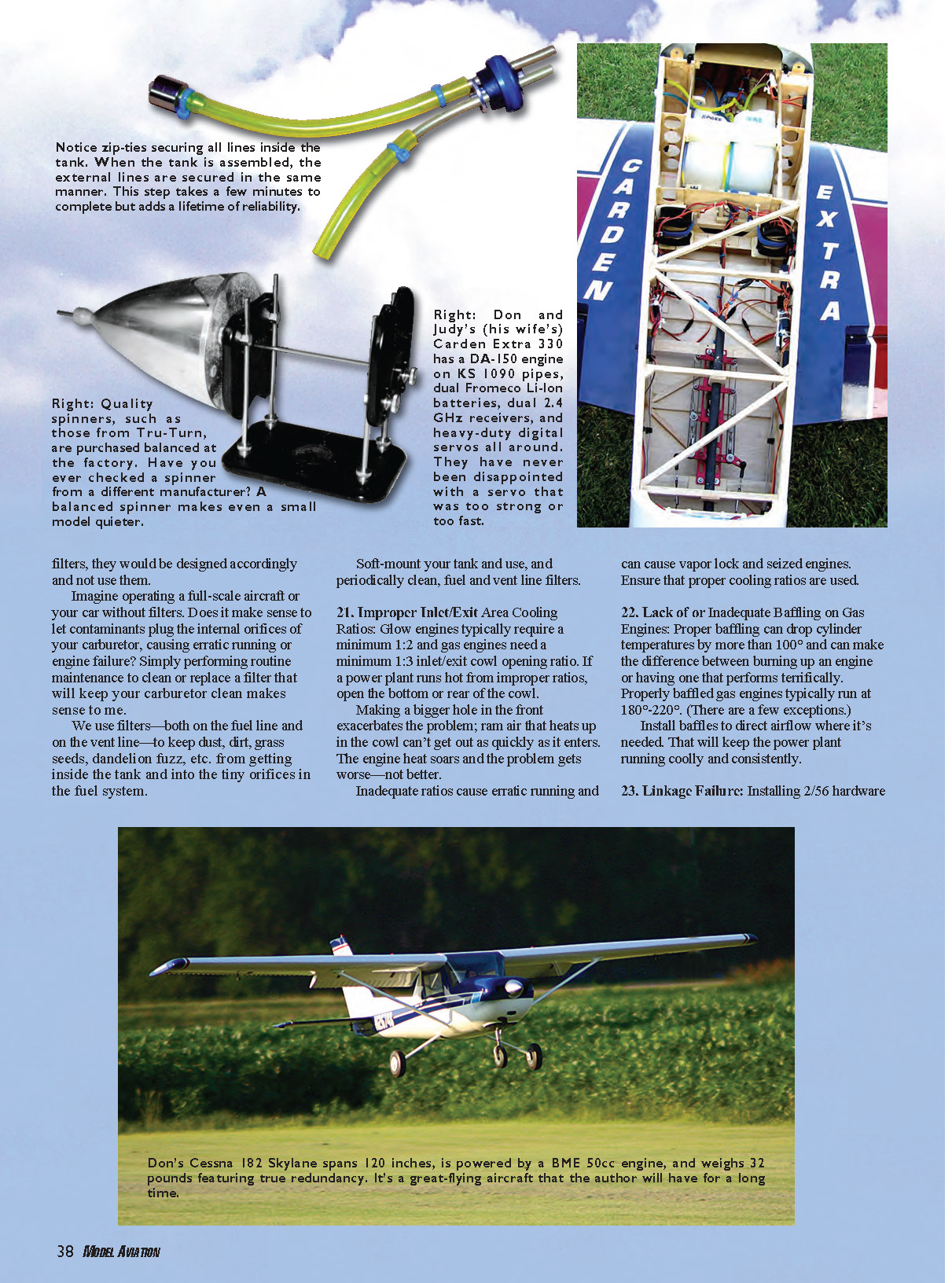
All connections should be secured. Inspect your tank and replace tubing once each year. Soft-mount tanks and ensure that vent and pickup lines are not blocked. Secure all connections, inside and outside, with zip-ties. Inspect your model's tank plumbing regularly.
20. Inadequate Fuel Filtering
Some aeromodelers don't employ filters. If internal-combustion engines ran consistently without filters, they would be designed accordingly and not use them.
Imagine operating a full-scale aircraft or your car without filters. Does it make sense to let contaminants plug the internal orifices of your carburetor, causing erratic running or engine failure? Simply performing routine maintenance to clean or replace a filter that will keep your carburetor clean makes sense.
We use filters—both on the fuel line and on the vent line—to keep dust, dirt, grass seeds, dandelion fuzz, etc., from getting inside the tank and into the tiny orifices in the fuel system.
Soft-mount your tank and use, and periodically clean, fuel and vent line filters.
21. Improper Inlet/Exit Area Cooling Ratios
Glow engines typically require a minimum 1:2 inlet/exit cowl-opening ratio and gas engines need a minimum 1:3 ratio. If a power plant runs hot from improper ratios, open the bottom or rear of the cowl.
Making a bigger hole in the front exacerbates the problem; ram air that heats up in the cowl can't get out as quickly as it enters. The engine heat soars and the problem gets worse—not better.
Inadequate ratios cause erratic running and can cause vapor lock and seized engines. Ensure that proper cooling ratios are used.
22. Lack of or Inadequate Baffling on Gas Engines
Proper baffling can drop cylinder temperatures by more than 100°F and can make the difference between burning up an engine or having one that performs terrifically. Properly baffled gas engines typically run at 180°–220°F (there are a few exceptions).
Install baffles to direct airflow where it's needed. That will keep the power plant running coolly and consistently.
23. Linkage Failure
Installing 2/56 hardware or plastic servo arms on high-performance models is an accident waiting to happen. Nylon servo arms get brittle with age and break, as do the teeth in your servo. Metal arms with 4-40 bolt-on ball links are the size of choice for Giant Scale airplanes.
Carbon-fiber pushrods or titanium turnbuckles are typically used for linkages, along with machined metal 4-40 servo arms tapped for 4-40 linkages.
Don't use welding rod (are these heat-treated, high-tensile, low-tensile, carbon-steel, low-carbon-steel rods? Most people don't know) or homemade threaded coat-hanger wire. Don't laugh; I've had more than one call about that.
Nylon rods that flex are simply unacceptable as pushrods on Giant Scale, high-performance aircraft and are conducive to flutter failure. If you have "gotten away with" using them, you are on borrowed time.
Does it make sense to build a $3,000–$6,000 model and save a few dollars on control linkages by using junk for a primary control? Of course it doesn't. Use properly set-up, high-quality linkage hardware to avoid linkage failure.
24. Loose Hardware and Metal-to-Metal Noise
Rattling metal parts such as loose mufflers, engine bolts, landing gear, and tail wheels or similar components will cause glitching or a lockout on 72 MHz systems. Lack of locking devices on threaded items or not periodically checking for threaded items that have loosened will cause the same metal-to-metal noise.
Make sure there is no metal-to-metal rattling; thread-lock your nuts, bolts, and screws; and periodically check them for tightness. We use space-age thread lock, which is used on full-scale aircraft and is approved by the FAA for use in high-vibration areas.
25. Hooking Up or Programming Control Surfaces Backward
This is a setup/preflight issue, and it can be avoided merely by testing control movement and direction before starting an engine.
Remember that when the stick is moved to the right, the right aileron should go up as viewed from the pilot's seat, and vice versa. Check controls before every flight.
26. Not Connecting Extension Cords Before Flight
This is another preflight issue, and it makes many expert pilots feel like toddlers. A simple control check before startup will identify this problem.
27. Vapor Lock
Fuel vaporizes because the airflow through the cowl is insufficient, either because of poor or no baffling or inadequate baffling. In fuel lines that are too close to mufflers, the fuel can vaporize, causing engine failure.
Ensure that air flows through the cowl and over fuel lines. If you experience vapor lock, reposition fuel lines away from mufflers or headers. Wrap aluminum foil around fuel lines, make sure that you use proper inlet/exit cowl ratios, and ensure that proper baffling is in place.
28. Improper Charge Rates for Batteries
There are all kinds of high-end chargers on the market for a variety of batteries. Some are programmable and some are not.
I get regular calls from aeromodelers who don't know that they programmed the wrong settings into their chargers and ruined batteries, or whose batteries caught fire because of incorrect settings. The battery is blamed when the cause is applying an incompatible charge rate.
Review charging instructions and program correct settings so you don't create a fire hazard or severely shorten the life of the pack, which is the heart of your aircraft.
Another typical mistake is to undercharge airborne batteries and not load-test batteries before every flight. The undercharge is caused by faulty chargers that predict a peak cutoff too early or charger rates that are set incorrectly.
Not all batteries are created equal, and the user sometimes neglects to burn in or test-cycle the pack. This results in a model running out of battery capacity sooner than predicted or, worse, can cause a crash because the pilot lacked a battery redundancy system.
Don't guess. Make sure you understand the battery technology and charger you are using, and charge accordingly. Test batteries as frequently as necessary to know how much power is consumed during a flight. A change in test results should coincide with flight demands or alert you that a pack is failing.
29. Incorrect CG
Tail-heavy models rarely fly twice. Nose-heavy airplanes are more likely to survive a test flight.
Ensure that your aircraft's CG is properly set before the test flight. The tank should be empty when you do so.
You can easily check a large model's CG with an EZ Balancer from Southwest Systems. Despite what some might tell you, the airplane requires the same balance point whether it's powered by a motor or an internal-combustion engine.
30. Incorrect Control Travels
Models have crashed because of too little or too much travel used on test flights. Many pilots have buried their Giant Scale airplanes on maiden flights because of too much travel.
Thousands of dollars worth of aircraft are needlessly destroyed because of excessive travel programmed into them. And neither the model nor the pilot (sometimes both) likes it enough to handle a landing.
If you don't know the correct travels, use 8°–10° for low rate and 15°–18° for high rate. These are safe settings to use on test flights. As the airplane progresses through trimming flights, you can adjust the settings for personal taste and optimum performance.
This travel guide makes the assumption that an aircraft's CG, incidence, and thrustline locations are correct. Check travels with a deflection meter before the first test flight.
Crashing is a choice. Those who do nothing to address deficiencies will keep crashing models and endangering others. I hope no one gets hurt if the pilot makes the wrong choices.
Correcting problems makes airplanes safer and more reliable, allowing their pilots to fly with confidence and safely land them if a malfunction occurs. It is the aeromodeler's responsibility to evaluate the information presented, make the appropriate decisions relative to his or her situation/setup, and safely operate the aircraft.
Mistakes do happen, but crashes should clearly be the exception rather than the rule. If you effectively address the issues I have presented, your models never have to crash.
Fly safely! MA
Don Apostolico [email protected]
Sources
- Southwest Systems
(805) 527-6337 www.ezbalancer.com
- Don's Hobby Shop
(800) 972-6273 www.donshobbyshop.com
Transcribed from original scans by AI. Minor OCR errors may remain.

