
The Rest of the Engine
by Frank Granelli
Sometimes we become so involved with the various types of model engines, performance ratings, and displacements that we overlook something important. Just as a fully race-prepared car engine is useless until its power is transmitted to the ground, a model engine is useless until its power is transmitted to the air. Most often, model aircraft use propellers for this job. Our engines also need to burn fuel to produce power, and they need to ignite that fuel. These functions, which are directly connected to the engine, are this month's subject.
Propellers
A model's engine is only as good as its propeller. The propeller's size, shape, and composition determine how much of the engine's power is transmitted to the air and the manner in which the aircraft can best use that power. The best combination of propeller characteristics for a particular model is a compromise. The pilot must choose a propeller that produces the best performance based on the aircraft's mission (training, racing, aerobatics, combat, etc.), the engine's power range, and the flying-field conditions.
A racing airplane would do best if its propeller were designed solely to produce high airspeeds while rotating at the same rpm at which the engine produces maximum horsepower. This is the right choice even if durability, climb, and acceleration rates are sacrificed.
Choosing the right propeller requires understanding and a few prop tips, one of which is that a propeller's blade rigidity is important. A propeller is nothing more than a rotating wing. All propellers have airfoil shapes and direct their lift in a horizontal path, called thrust, instead of a vertical direction, as does the aircraft's main wing. Thrust pulls the aircraft forward.
Imagine how much of your aircraft's wing lift would be lost if the outer third of the wing were to flex enough that its incidence—its angle of attack (AOA) to the oncoming airstream—significantly decreased during every turn or climb. In the same way, a propeller in which the tips flex does "flatten out," reducing its incidence during acceleration and climb, thereby losing thrust when it is most needed. Unlike a wing, which develops lift along almost its entire span, a rotating propeller produces the majority of its thrust centered around the 75% point of each blade's length. This makes the thrust lost because of tip flexing even more critical.
Stand slightly behind and to the side of the spinning propeller and watch the tips. If they follow a wavy path, that signals excessive pitch loss (lower propeller AOA), which results in power lost transferring the engine's energy to the air.
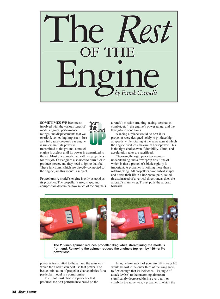
The first 20% of a propeller blade's length—its span—produces much drag but little thrust. This section is the area where the propeller's round center—the hub—tapers into the working "wing" of the blade, which does all the work. There is little "wing area" here. This area also moves the slowest through the air since it is closest to the center of the disc formed by the rotating propeller. However, this inner section does rotate and therefore produces air drag. This is why spinners make propellers more efficient. The next 50% of the blade's span is the area where the leading-edge-to-trailing-edge width (the chord) increases to maximum and the airfoil becomes fully developed. Some thrust is lost until the blade is fully formed, and more is lost because the center section rotates more slowly than the remaining outer blade area. Since a wing's total lift depends, in part, on its airspeed, the lift produced by different blade sections depends a great deal on their rotational speeds.
How different are these rotational speeds? The blade section 1 inch out from the hub of an 11-inch-diameter model propeller rotating at 11,000 rpm has an "airspeed" of just 96 feet per second (fps), or 60 mph. The middle of the blade is rotating through the air at 260 fps, or 180 mph, and the 75% point is moving at 396 fps, or 264 mph.
Even though the blade's area near the tip (90%) is much less than that near the middle, it is moving nearly twice as fast—475 fps, or 317 mph—and is therefore producing more thrust than the center section.
Please study that last rotational speed. The tip itself is moving at 530 fps, which is approximately the same speed as some .45-caliber bullets. If you want to know what happens if you are careless enough to put a hand into a spinning model propeller's arc, envision pointing a Colt .45 at your hand and pulling the trigger. Not an attractive image.
Please be careful. Tune your engine while standing behind the propeller, never stand directly to the side of a spinning propeller, and keep children away from your engine at all times.
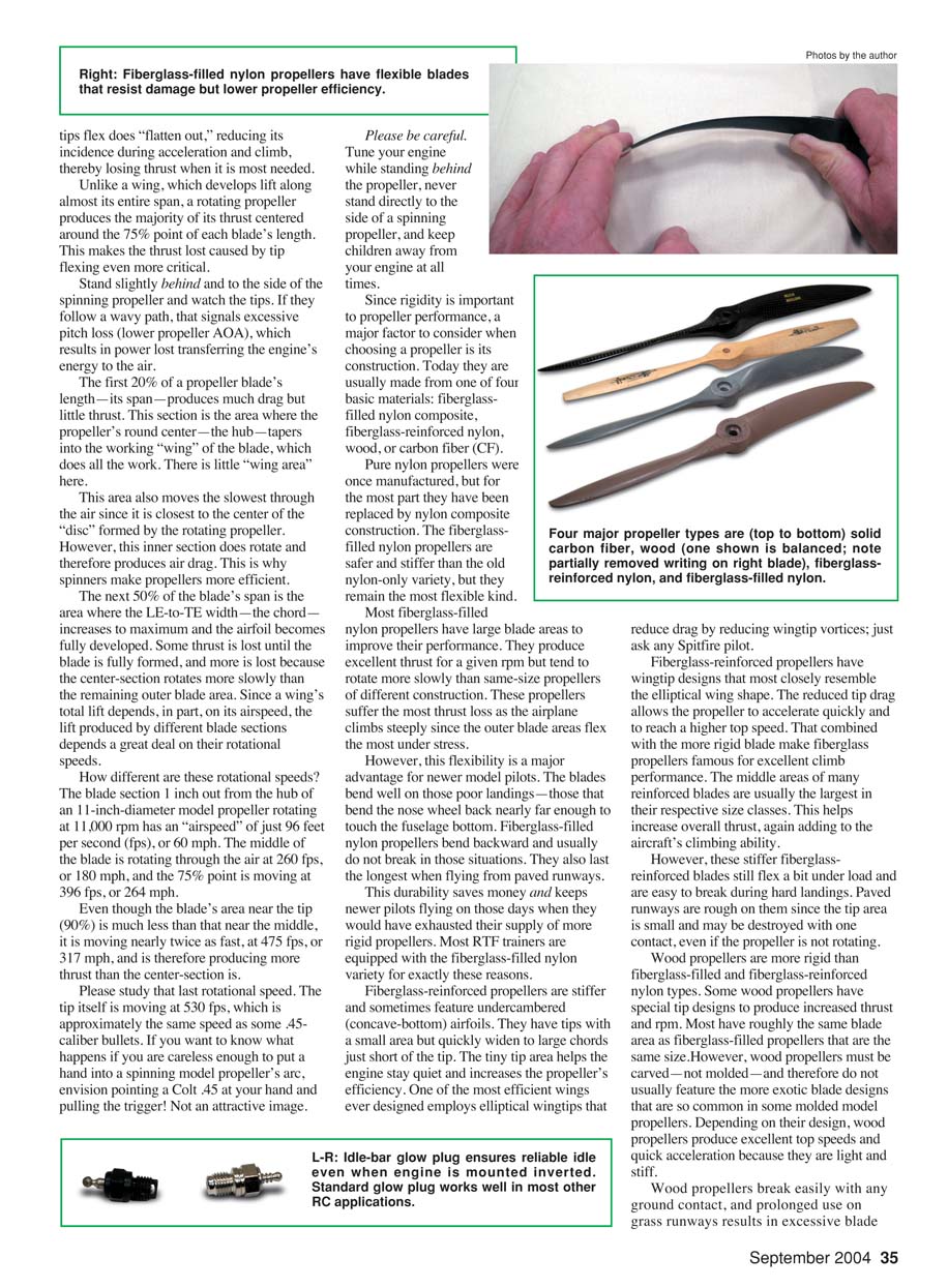
Since rigidity is important to propeller performance, a major factor to consider when choosing a propeller is its construction. Today they are usually made from one of four basic materials:
- Fiberglass-filled nylon composite
- Fiberglass-reinforced nylon
- Wood
- Carbon fiber (CF)
Pure nylon propellers were once manufactured, but for the most part they have been replaced by nylon composite construction. Fiberglass-filled nylon propellers are safer and stiffer than the old nylon-only variety, but they remain the most flexible kind.
Most fiberglass-filled nylon propellers have large blade areas to improve their performance. They produce excellent thrust for a given rpm but tend to rotate more slowly than same-size props of different construction. These propellers suffer the most thrust loss as the airplane climbs steeply since the outer blade areas flex the most under stress.
However, this flexibility is a major advantage for newer pilots. The blades tend to take on those poor landings—those that bend the nose wheel back nearly far enough to touch the fuselage bottom. Fiberglass-filled nylon propellers bend backward and usually do not break in those situations. They also last the longest when flying from paved runways. This durability saves money and keeps newer pilots flying on those days when they would have exhausted their supply of more rigid propellers. Most RTF trainers are equipped with the fiberglass-filled nylon variety for exactly these reasons.
Fiberglass-reinforced propellers are stiffer and sometimes feature undercambered (concave-bottom) airfoils. They have tips with a small area but quickly widen to large chords just aft of the tip. The tiny tip area helps the engine stay quiet and increases the propeller's efficiency. One of the most efficient wings ever designed employs elliptical wingtips that reduce drag by reducing wingtip vortices—just ask any Spitfire pilot.
Fiberglass-reinforced propellers have wingtip designs that most closely resemble the elliptical wing shape. The reduced tip drag allows the propeller to accelerate quickly and to reach a higher top speed. That, combined with the more rigid blade, makes fiberglass propellers famous for excellent climb performance. The middle areas of many reinforced blades are usually the largest in their respective size classes. This helps increase overall thrust, again adding to the aircraft's climbing ability.
However, these stiffer fiberglass-reinforced blades still flex a bit under load and are easy to break during hard landings. Paved runways are rough on them since the tip area is small and may be destroyed with one contact, even if the propeller is not rotating.
Wood propellers are more rigid than fiberglass-filled and fiberglass-reinforced nylon types. Some wood propellers have special tip designs to produce increased thrust and rpm. Most have roughly the same blade area as fiberglass-filled propellers that are the same size. However, wood propellers must be carved—not molded—and therefore do not usually feature the more exotic blade designs that are so common in some molded model propellers. Depending on their design, wood propellers produce excellent top speeds and quick acceleration because they are light and stiff.
Wood propellers break easily with any ground contact, and prolonged use on grass runways results in excessive blade wear. They also require the most balancing effort because density and water content may vary in a single propeller.
You know that all propellers must be balanced, right? Unbalanced propellers cause excessive vibration, resulting in three major problems:
- The engine's bearings wear quickly.
- Onboard radio components, especially servos, suffer excessive wear and can fail early. Whenever a servo quits in flight, much of the fun of flying RC models is diminished.
- An unbalanced propeller will cause a 3%–4% rpm loss. An engine that would have turned a balanced propeller at 11,000 rpm turns an unbalanced propeller at only 10,600 rpm. Climb rate and aerobatic performance are reduced.
Many different propeller balancers are available. I will cover these in the last edition of this segment of the series.
CF propellers are the ultimate in rigidity; they have almost no detectable flex. They can assume any airfoil shape and blade area as they are molded. Some are solid and others are hollow. CF propellers are light, allowing for the fastest engine acceleration possible; hollow ones accelerate even more quickly. Both solid and hollow CF props feature excellent performance across the entire aerobatic spectrum. You can even purchase them prebalanced.
However, despite their superior performance, few modelers use CF propellers. There are two good reasons for this. The first is cost: CF propellers vary from nearly $30 to $120 for the larger sizes. A modeler can buy an abundance of wood, fiberglass-filled, or fiberglass-reinforced propellers for $30.
Second, trainers and many lower-performance sport models are unable to take full advantage of the performance increase that such a propeller provides. From level flight, a 40-size trainer may be able to perform a 100-foot vertical climb. If a CF propeller provides a 15% climb increase, that trainer will perform a 115-foot vertical climb. It's not that noticeable for the money.
But install that propeller on a 40-size Pattern airplane, and its normal 250-foot vertical climb stretches to nearly 300 feet with enough remaining airspeed to provide excellent control.
After construction, the next important factor in picking the right propeller is size. Two numbers label their dimensions: the first is diameter in inches. The second number is pitch, which represents the distance in inches the propeller would travel forward in one revolution if there were no friction, drag, or other limiting factors. This is the propeller's AOA, or incidence.
The numbers are separated by the usual "by" designation: "x." An 11-inch-diameter propeller with a 6-inch pitch is called an "11 x 6."
Understanding both numbers' performance implications is critical. They interact in a complicated dance of airflow, engine performance, thrust, and geometry.
Fortunately the dance becomes easy to understand once you know a few simple steps.
- Disc area (diameter) vs. speed: The propeller's efficiency for a given task is determined by the amount of air it moves per revolution and its speed. On a sport airplane, if a propeller can move a huge amount of air, but only at a slower speed, that is better than moving small amounts of air at high speeds. The diameter of the disc that the rotating propeller produces has more effect on the power transmitted than a speed increase does because the disc area increases by the square of the radius. Therefore, an increase in diameter moves additional amounts of air by the square of the radius. This is a large force multiplier. As long as you have enough pitch to fly at the speed you need, diameter is king—offering faster acceleration, better climb, and shorter takeoff runs.
- Pitch depends on the airframe: The pitch determines airspeed only in combination with the airframe. A 20-inch-pitch propeller sounds fast. But if the airframe has a high level of aerodynamic drag, fixed landing gear, and straight wings, this drag prevents the airplane from ever reaching the propeller's theoretical top speed. The result is that the propeller cannot reach its maximum rpm because the extra airframe drag increases the propeller's air load.
- The practical compromise: The best propeller size for a given engine in a 40- to 60-size, high-drag sport RC model is the compromise between the largest diameter and highest pitch that still allows the engine's maximum ground rpm to be roughly 1,000–1,500 rpm higher than its high-torque (maximum twisting power) rpm. (This figure is after the high-speed mixture has been adjusted to be about 500 rpm less than absolute peak.)
Why this rpm? Once the airplane is flying, there is an average increase of about 500 rpm because the aircraft's forward speed reduces the propeller's AOA. Another way to picture this is that the flowing air into the propeller from the front is helping the propeller; it is decreasing the engine's workload by reducing the effective AOA.
An airplane tops flying faster when the propeller's AOA nears zero. But once the aircraft's nose is pointed skyward, more of its weight is placed on the propeller and therefore on the engine's turning ability. The propeller's rpm drops, the engine's load increases with the increasing AOA, and those 500 "free" rpm disappear as propeller drag increases with the escalating AOA.
The stress of pulling the aircraft upward increases the power demands on the engine. It responds by turning more slowly, just as a car’s engine does when going up a steep hill until extra energy, in the form of stepping on the gas, is applied. But the model engine is already at full power; there is no extra “gas” to give.
In fact, the engine’s rpm will drop until it reaches its high-torque rpm. If the engine is the right size for the airplane and the climb angle is not steeper than what the engine/airframe combination was designed to maintain (usually at least 45°), the rpm reduction stops here and the airplane maintains a constant climb rate.
Why not use a propeller that allows the engine to rotate at its peak horsepower rpm? The horsepower ratings for most .40–.60 two-stroke engines are usually at so high an rpm that they are nearly unusable for sport applications. Most reach peak horsepower well in excess of 13,000 rpm.
At those rpms, model pilots do not need to worry about their airplanes’ performance because most clubs won’t let them fly such loud models. Even if they can fly them, the propeller disc must be so small—7–9 inches—that little thrust can be applied to the air. The result is an inefficient propeller, an airplane flying roughly 35 mph, and a screaming engine trying to tear itself apart.
Experienced RC modelers have known this “great truth” for years—many times without even knowing they know it—but they have had no data to support their intuitive propeller choices. So I set out to prove this last step.
I used a relatively new tool to gather the needed data. The RC Flight Data Recorder manufactured by Eagle Tree Systems records airspeed, rate of climb, climb angle, altitude, and servo performance during flight. It can also record in-flight engine rpm and temperatures, but these systems were not installed on the test aircraft.
The recorder correlates flight data and transmitter inputs over time. This lets the pilot know what was happening and when. I have been using this instrument for some time when evaluating aircraft for MA’s Sport Aviator online magazine (www.masportaviator.com) and have become familiar with interpreting the reported data. I used my trusty, many-year-old SuperStar 40 trainer equipped with an even older .45 engine.
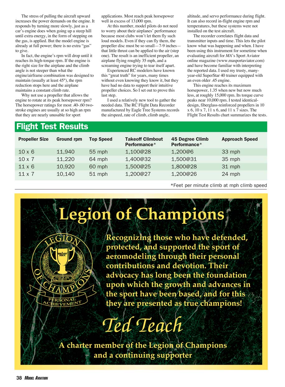
This engine reaches its maximum horsepower—about 1.35 hp when new, but now much less—at roughly 15,000 rpm. Its torque curve peaks near 10,000 rpm. I tested identical-design, fiberglass-reinforced propellers in 10 x 6, 10 x 7, 11 x 6, and 11 x 7 sizes. The flight test results follow.
Flight Test Results
- Propeller: 10 x 6
Ground rpm: 11,940 rpm Top speed: 55 mph Takeoff climbout: 1,100 fpm @ 28 mph 45° climb: 1,200 fpm @ 26 mph Approach speed: 33 mph
- Propeller: 10 x 7
Ground rpm: 11,220 rpm Top speed: 64 mph Takeoff climbout: 1,400 fpm @ 32 mph 45° climb: 1,500 fpm @ 31 mph Approach speed: 35 mph
- Propeller: 11 x 6
Ground rpm: 10,920 rpm Top speed: 60 mph Takeoff climbout: 1,500 fpm @ 25 mph 45° climb: 1,800 fpm @ 28 mph Approach speed: 31 mph
- Propeller: 11 x 7
Ground rpm: 10,140 rpm Top speed: 51 mph Takeoff climbout: 1,200 fpm @ 27 mph 45° climb: 1,200 fpm @ 26 mph Approach speed: 24 mph
Note: climb figures are in feet per minute at the indicated climb speed (mph).
As shown, the highest ground rpm does not translate into the fastest airspeed or the best climb rate. Under the demands of a climb, the smaller 10-inch propeller discs could not transfer the engine’s power to the air as effectively as the 11-inch discs could.
An inch may not seem like a big difference. However, the 11-inch propeller has an effective area of 95 square inches versus the 10-inch propeller’s 79 square inches. The engine’s "force area" is about 20% larger using the 11-inch propeller.
The larger disc is the reason why the 11 x 6 propeller produced a 20% better climb rate than the 10 x 7, despite the slower climb speed. The extra power required to turn the 11 x 7 propeller when climbing proved more than the engine could deliver. Climb and top speed suffered, but landing speed was the slowest, probably because the idle speed was less than 2,100 rpm. The 11 x 7 might cause engine overheating in hot weather.
The 11 x 6 allowed the aircraft to leave the ground in the shortest time at the slowest airspeed, reducing airframe wear. It produced a climb rate up to 50% higher, and its top speed was only 6% less than the highest but up to 18% higher than the remaining propellers. During your next visit to the flying field, check the propellers on most .45 two-stroke engines. Most will be various types of 11 x 6s.
Choose the propeller-and-glow-plug combination that permits the engine to turn the largest-diameter propeller approximately 1,000–1,500 rpm higher than its peak torque speed on the ground. Start with the largest diameter and lowest pitch recommended for your engine. If the engine will not turn this propeller fast enough, drop to the next smaller diameter, again with the lowest pitch. Increase the pitch if the engine turns too fast. Continue until you find the right size combination.
Typical propeller diameter guidelines for sport models:
- .30-size engines: usually use a 9-inch-diameter propeller
- .40-size engines: up to 10.5 inches
- .45-size engines: commonly 11 inches
- .60-size engines: work best with a 12-inch propeller
Remember that these recommendations are for sport models only.
Glow Plugs
Did I also mention the glow plug? It causes the fuel to burn and release its energy. Fortunately there are only two types of glow plugs that newer sport-model pilots need to know about.
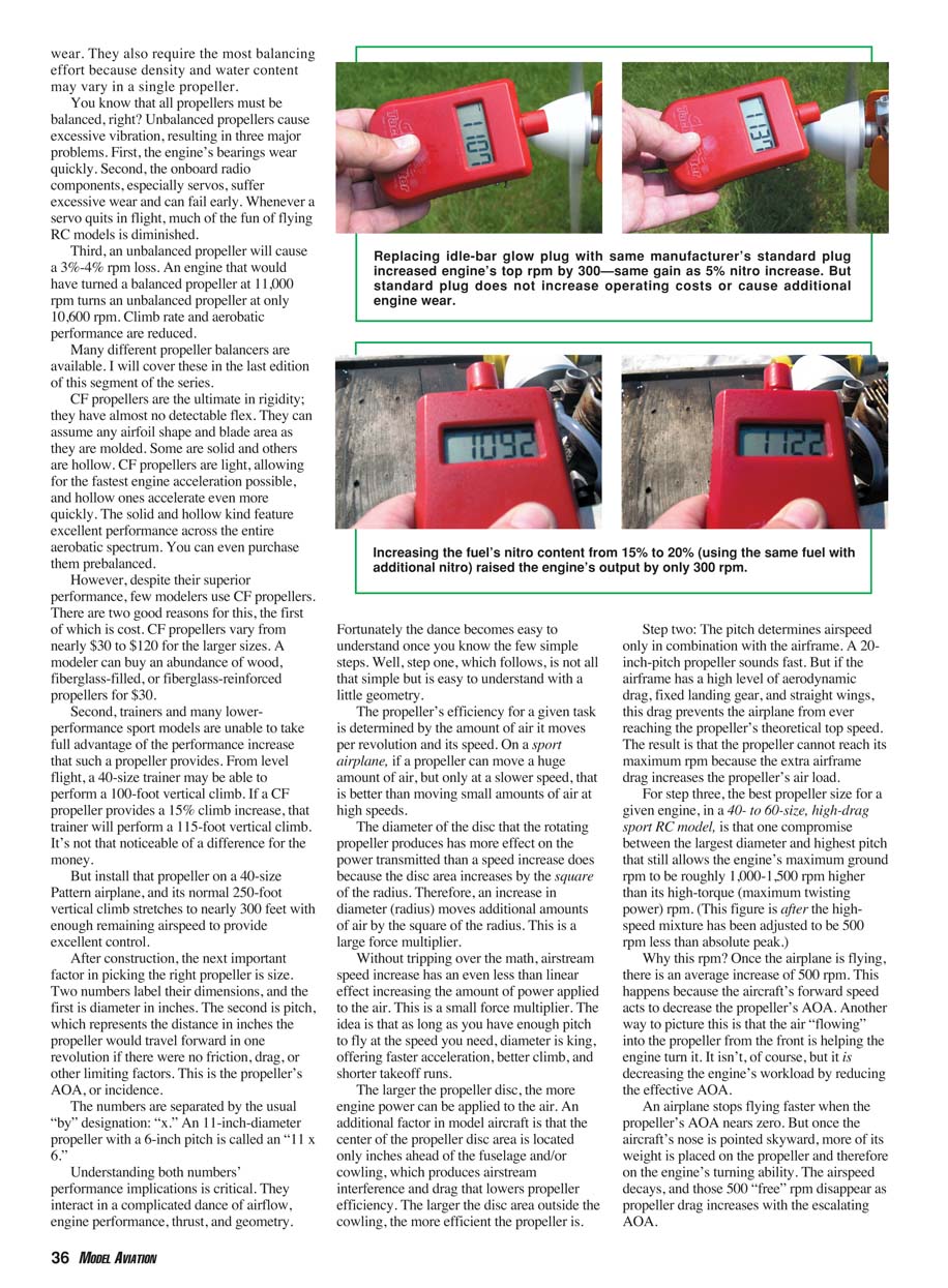
The idle-bar plug was once the only design that provided a reliable idle. The metal bar protected the glow element from unburnt liquid fuel that otherwise cooled the element to lower than the fuel’s ignition temperature at idle speeds. The bar itself became extremely hot, adding protection to the glow element’s idle temperature.
But today’s more powerful sport engines are equipped with mufflers that preserve the chamber’s heat at idle. Modern carburetors allow finer adjustment of the fuel/air mixture, reducing the amount of liquid, unburnt fuel that enters the chamber at idle speeds. Therefore, idle-bar glow plugs are not always required on newer sport engines.
Fuel
Choosing the right fuel is the last critical factor to ensure that your new two-stroke engine gets the best performance and longest life. The “right” fuel is also one of the most controversial, opinion-rich, and individualistic subjects in model aviation. But there are some useful guidelines to remember.
Two-stroke fuel has three major ingredients: methanol, lubricating oil, and nitromethane (nitro).
- Methanol comprises about 60%–75% of most fuels. It burns completely and adds to the fuel’s total energy output.
- The lubricating oil comprises roughly 20% of the fuel. Most two-stroke fuels contain two types of oil: 4%–8% is usually castor oil and the remaining 12%–16% is a synthetic that varies by manufacturer. Oils typically do not burn completely, and what small percentage of the oil that does burn does so at lower energy levels than methanol. Castor oil is used because it maintains a lubricating film at higher temperatures than synthetic oils and provides a degree of protection against detonation. Synthetic oils provide cleaner running, less exhaust residue, and generally longer engine life when used in the proper amounts and blends for your engine. Manufacturers often publish recommended oil types and percentages for their engines; follow those recommendations for best results.
- The third fuel component is nitromethane. It burns at a higher energy level than methanol. However, it also produces higher combustion-chamber temperatures and therefore needs to be limited. Most sport fuels contain 5%–25% nitro. It prolongs the combustion event. The burning process takes longer, and that also produces more energy.
Many pilots overrate the power increase obtained by "upping the nitro" in their sport engine’s fuel. Tests show how little effect higher nitro content has on sport engines. Raising nitro content by 5% in a fuel produced only about a 300 rpm gain. But nitro does improve an engine’s idling ability, permitting a lower reliable idle speed. Therefore, consider nitro contents in the 10%–15% range as a good sport-flying compromise.
There is such a thing as too much nitro for a given engine. If the combustion event becomes too prolonged, detonation may occur. You may hear pinging (a sound like frying eggs), or the exhaust note may become very loose. Unless operating at high altitudes—exceeding 5,000 feet—there is little reason to use fuels with nitro contents higher than 20%.
Next month I’ll cover some of the differences and advantages of four-stroke engines. Since model engines do not run for long periods without an onboard fuel supply, I’ll also cover fuel-tank choices and installation requirements.
MA
Frank Granelli 24 Old Middletown Rd. Rockaway, NJ 07866
Transcribed from original scans by AI. Minor OCR errors may remain.

