
Retro RC 1913 Eastbourne Monoplane
Terry Dunn [email protected]
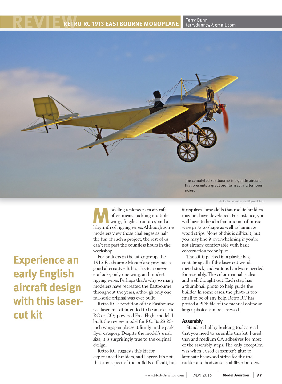
Modeling a pioneer-era aircraft often means tackling multiple wings, fragile structures, and a labyrinth of rigging wires. Although some modelers view those challenges as half the fun of such a project, the rest of us can't see past the countless hours in the workshop.
For builders in the latter group, the 1913 Eastbourne Monoplane presents a good alternative. It has classic pioneer-era looks, only one wing, and modest rigging wires. Perhaps that's why so many modelers have recreated the Eastbourne throughout the years, although only one full-scale original was ever built.
Retro RC's rendition of the Eastbourne is a laser-cut kit intended to be an electric RC or CO2-powered Free Flight model. I built the review model for RC. Its 28.25-inch wingspan places it firmly in the park flyer category. Despite the model's small size, it is surprisingly true to the original design.
Retro RC suggests this kit for experienced builders, and I agree. It's not that any aspect of the build is difficult, but it requires some skills that rookie builders may not have developed. For instance, you will have to bend a fair amount of music wire parts to shape as well as laminate wood strips. None of this is difficult, but you may find it overwhelming if you're not already comfortable with basic construction techniques.
Assembly
Kit contents and manual
- The kit is packed in a plastic bag containing all the laser-cut wood, metal stock, and various hardware needed for assembly.
- The color manual is clear and well thought out. Each step has a thumbnail photo to help guide the builder. In some cases the photo is too small to be of much help; Retro RC has posted a PDF of the manual online so larger photos can be accessed.
Tools and adhesives
Standard hobby building tools are all that you need. I used thin and medium CA for most steps and carpenter's glue to laminate basswood strips for the rudder and horizontal stabilizer borders.
One thing I like about the manual is that it has you cover subassemblies as they are completed. For example, the tail feathers are the first parts built and they are covered before work on the fuselage begins. Having a finished part on the workbench motivates me to keep the build moving and prevents a marathon covering session at the end.
Landing gear and wheels
The landing gear design is surprisingly accurate; even the tail skid is strikingly similar to the full-scale airplane. The wheels are made of assembled wooden hubs with rubber O-ring tires — the overall effect is convincing. The landing gear has built-in shock absorption but is slightly stiff; grease it in to prevent bouncing on paved runways.
Covering and finishing
The open structure in the rear of the fuselage must be covered. I used Stevens AeroModel AeroLITE antique white covering for the rear fuselage, wing, and tail surfaces. AeroLITE is lightweight and shrinks well over compound curves.
I applied brown craft paint as if it were a stain to the sheeted fuselage parts: paint an area, then immediately wipe off the excess with a clean rag. I used the same technique on exposed wooden parts such as wheel struts, tail skid, and control horns. The silver-looking areas of the fuselage were covered in AeroLITE and then painted with silver spray paint.
Before adding the rigging, I sprayed all covered areas with a light coat of flat clear to remove the shiny finish of the AeroLITE and give the airplane a more authentic look.
Fuselage alignment
I apparently built the fuselage with a slight twist from front to back. This became evident when I attempted to mount the horizontal stabilizer: when sitting flat on the rear part of the fuselage, the stabilizer was noticeably out of alignment with the wing-mounting tubes. I shimmed the stabilizer to rest level with the forward part of the fuselage and rigged the rudder to be perpendicular to the stabilizer.
Wing assembly
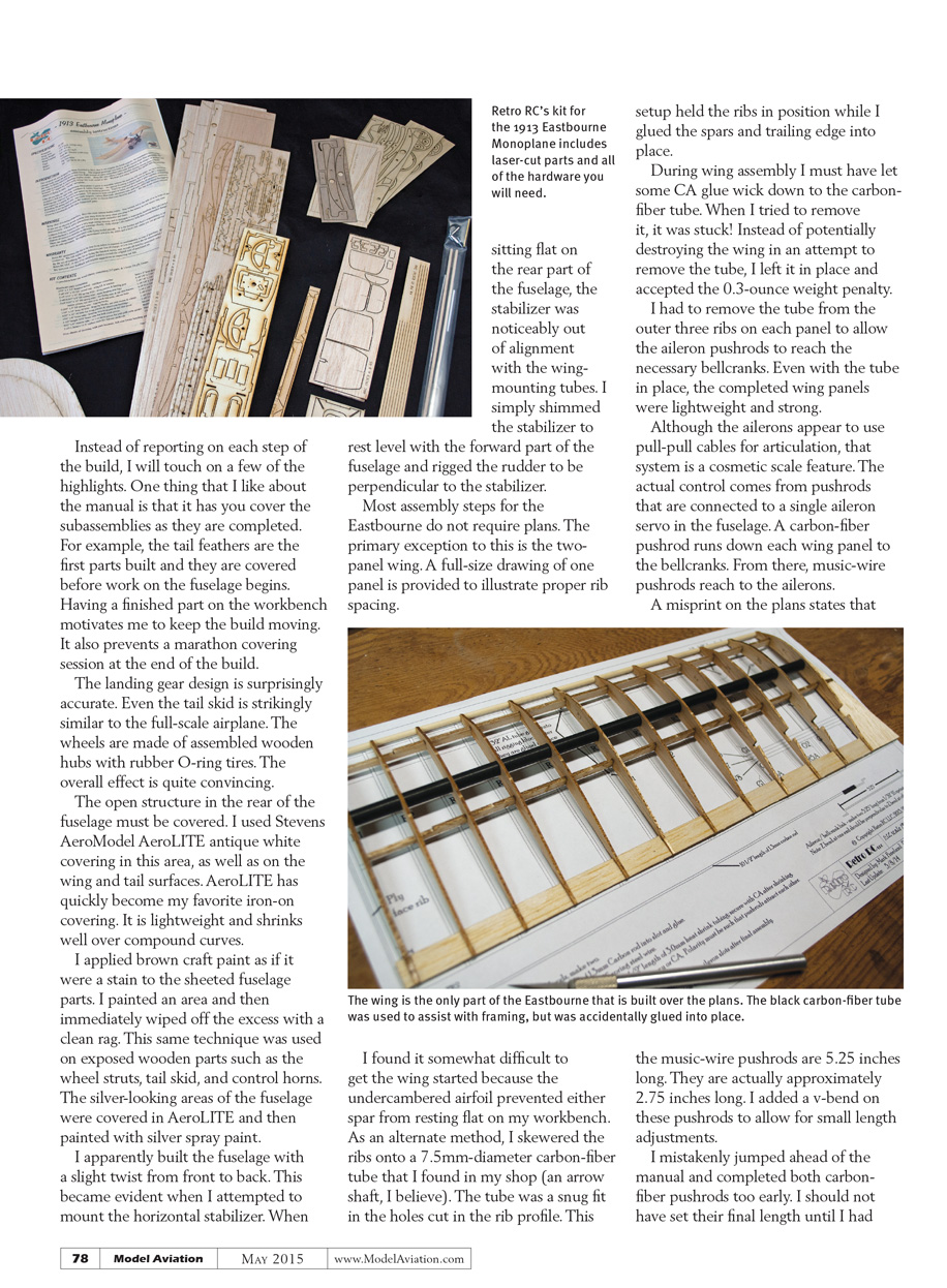
Most assembly steps do not require plans; the primary exception is the two-panel wing. A full-size drawing of one panel is provided to illustrate proper rib spacing.
Getting the wing started is somewhat difficult because the undercambered airfoil prevents either spar from resting flat on a workbench. As an alternate method I skewered the ribs onto a 7.5 mm-diameter carbon-fiber tube (an arrow shaft). The tube was a snug fit in the rib holes and held the ribs while I glued the spars and trailing edge.
During wing assembly some CA wicked down to the carbon-fiber tube and it became stuck. Rather than risk destroying the wing trying to remove the tube, I left it in place and accepted the 0.3-ounce weight penalty. I had to remove the tube from the outer three ribs on each panel to allow the aileron pushrods to reach the bellcranks. Even with the tube in place, the completed wing panels were lightweight and strong.
When mounting the wing to the fuselage, be sure both wing panels are at the same incidence. Mine were slightly off — perhaps another symptom of the fuselage twist — and required adjustment. This correction was easy to make and ensured the model would fly true.
Ailerons and control system
Although the ailerons appear to use pull-pull cables for articulation, that system is a cosmetic scale feature. Actual control comes from pushrods connected to a single aileron servo in the fuselage. A carbon-fiber pushrod runs down each wing panel to the bellcranks; from there, music-wire pushrods reach the ailerons.
A misprint on the plans states that the music-wire pushrods are 5.25 inches long. They are actually approximately 2.75 inches long. I added a V-bend to these pushrods to allow for small length adjustments.
I mistakenly jumped ahead of the manual and completed both carbon-fiber pushrods too early. I should not have set their final length until I had the music-wire pushrods at the control horns installed. I then installed the wings in place. Consequently, my pushrods were roughly 3/16 inch too short. I compensated for this by increasing the width of the block that connects the pushrods to the servo.
Servos, receiver, and rigging
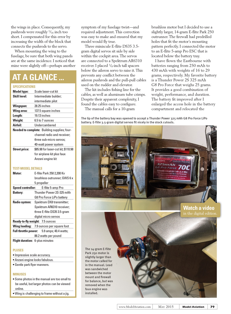
Three miniscule E-flite DS35 3.5-gram digital servos sit side by side within the cockpit area and are connected to a Spektrum AR6310 receiver. I placed 1/8-inch tall spacers below the aileron servo to raise it and prevent conflict between the aileron pushrods and the pull-pull cables used on the rudder and elevator.
The kit includes fishing line for the cables and aluminum tube crimps. Despite their apparent complexity, the cables were easy to configure.
Motor, ESC, and batteries
The manual calls for a 10-gram brushless motor, but I used a slightly larger 14-gram E-flite Park 250 outrunner. The firewall had predrilled holes that fit the motor’s mounting pattern perfectly. I connected the motor to an E-flite 5-amp Pro ESC located below the battery tray.
I have flown the Eastbourne with batteries from 250 mAh to 430 mAh, weighing 16 to 29 grams, respectively. My favorite is a Thunder Power 2S 325 mAh G8 Pro Force (25 grams) for its balance of weight, performance, and duration. The battery fit improved after I enlarged the access hole in the battery compartment and relocated the magnets that secure the battery hatch.
The power system pulls 5.9 amps and produces approximately 40 watts with a GWS 6 x 5 propeller, which I think is perfect for this airplane. The bright orange prop looked out of place, so I gave it a faux wood finish by coloring it with a brown Sharpie marker.
Final weight and balance
The completed model required 1/2 ounce of lead on the firewall for proper center of gravity. I sandwiched two 1/4-ounce lead slugs between the firewall and motor mount and painted them brown to match. This brought the final weight to 7.5 ounces.
Although that is heavier than the 6.5 ounces shown in the manual, some of the difference is attributable to my tube left in the wings. Despite being overweight, the wing loading and power loading values for the model were still promising.
Flying
I programmed my Spektrum DX8 transmitter with 30% exponential on all control surfaces and triple rates at 100%, 80%, and 60% for each surface.
All takeoffs were from paved or hard-dirt runways. With gradual throttle inputs, the Eastbourne predictably accelerates to flying speed and needs little rudder correction to stay straight. Full throttle results in a surprising and unscale-like change of speed, so that setting is best saved for climbouts. I spent most flight time at 50%–75% power for moderate speeds that showcase the model.
Initial aileron response was slow. I increased the high-rate throw to 125% and added a 30% rudder→aileron mix. With these adjustments the Eastbourne responds quicker while remaining docile.
I have not attempted aerobatics; although it may be capable, it doesn't seem right for this airplane. The Eastbourne is in its element performing slow, silent flybys and graceful sweeping turns.
With its light wing loading, the Eastbourne is best flown in calm conditions. I have flown it in 9–10 mph winds, but it wasn't much fun. Save this model for tranquil afternoons when the sun is low — it is relaxing to fly and casts a great silhouette.
Landing is as easy as you would expect from a lightly loaded slow flyer. There is plenty of drag to overcome, so I like to maintain a few clicks of power on final approach. Grease the landing gear to reduce stiffness and bouncing on paved runways.
Faux Engine
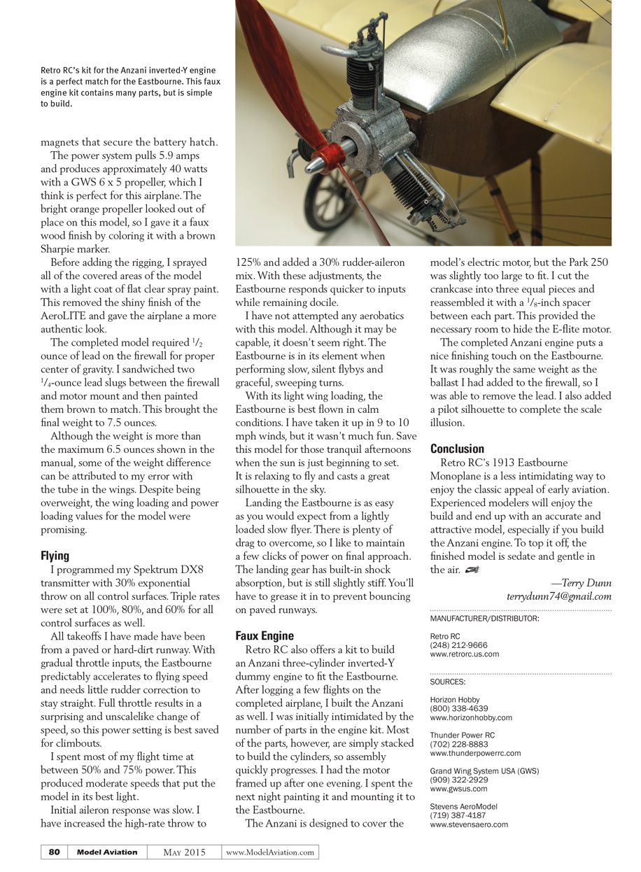
Retro RC also offers a kit to build an Anzani three-cylinder inverted-Y dummy engine to fit the Eastbourne. After logging a few flights I built the Anzani. I was initially intimidated by the number of parts, but most parts are simply stacked to build the cylinders, so assembly progresses quickly. I had the motor framed up after one evening and spent the next night painting it and mounting it to the Eastbourne.
The Anzani is designed to cover the model's electric motor, but the Park 250 was slightly too large to fit. I cut the crankcase into three equal pieces and reassembled it with a 1/8-inch spacer between each part to provide the necessary room to hide the E-flite motor.
The completed Anzani engine puts a nice finishing touch on the Eastbourne. It was roughly the same weight as the ballast I had added to the firewall, so I was able to remove the lead. I also added a pilot silhouette to complete the scale illusion.
Conclusion
Retro RC's 1913 Eastbourne Monoplane is a less intimidating way to enjoy the classic appeal of early aviation. Experienced modelers will enjoy the build and end up with an accurate and attractive model, especially if you build the Anzani engine. To top it off, the finished model is sedate and gentle in the air.
—Terry Dunn [email protected]
Manufacturer / Distributor
- Retro RC — (248) 212-9666 — www.retrorc.us.com
Sources
- Horizon Hobby — (800) 338-4639 — www.horizonhobby.com
- Thunder Power RC — (702) 228-8883 — www.thunderpowerrc.com
- Grand Wing System USA (GWS) — (909) 322-2929 — www.gwsus.com
- Stevens AeroModel — (719) 387-4187 — www.stevensaero.com
Transcribed from original scans by AI. Minor OCR errors may remain.

