
SUPER PEARL 202-E
An easy-to-build E-36 electric FF model
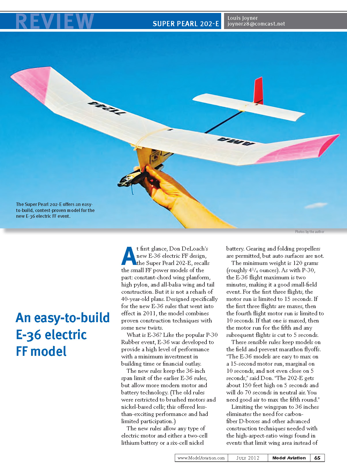
At first glance, Don DeLoach’s new E-36 electric FF design, the Super Pearl 202-E, recalls the small FF power models of the past: constant-chord wing planform, high pylon, and all-balsa wing and tail construction. But it is not a rehash of 40-year-old plans. Designed specifically for the new E-36 rules that went into effect in 2011, the model combines proven construction techniques with some new twists.
What is E-36? Like the popular P-30 Rubber event, E-36 was developed to provide a high level of performance with a minimum investment in building time or financial outlay.
Key points of the E-36 rules:
- Wingspan limit: 36 inches (same as earlier E-36 rules).
- Motors and batteries: any type of electric motor is allowed; either a two-cell lithium battery or a six-cell nickel battery may be used.
- Gearing and folding propellers are permitted; auto surfaces are not.
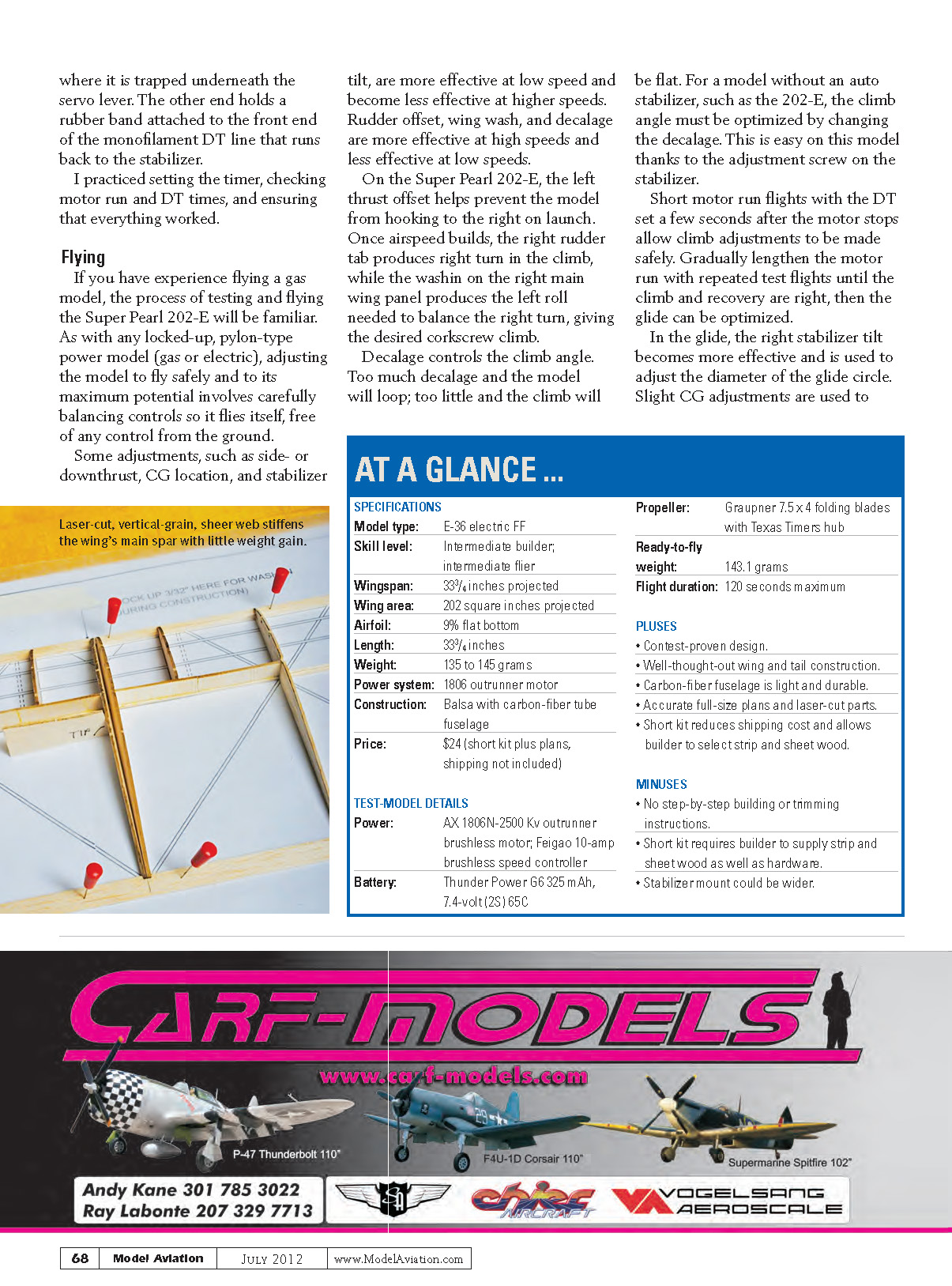
- Minimum weight: 120 grams (roughly 4 1/4 ounces).
- Flight maximum: two minutes per flight.
- Motor-run limits:
- First three flights: 15 seconds maximum motor run.
- If the first three flights are maxes: fourth flight motor run limited to 10 seconds.
- If the fourth is maxed: fifth and subsequent flights motor run limited to 5 seconds.
These rules keep models on the field and prevent marathon flyoffs. “The E-36 models are easy to max on a 15-second motor run, marginal on 10 seconds, and not even close on 5 seconds,” said Don. “The 202-E gets about 150 feet high on 5 seconds and will do 70 seconds in neutral air. You need good air to max the fifth round.”
Limiting the wingspan to 36 inches eliminates the need for carbon-fiber D-boxes and other advanced construction techniques required with high-aspect-ratio wings. A traditional balsa structure works fine. Typical E-36 dimensions and features:
- Wing chord: 5 1/2 to 6 inches.
- Overall length: roughly 30 inches.
- Airfoil: flat-bottomed, relatively thick for quick construction and stiffness.
- Trim: follows traditional gas-model trim — spiral climb to the right produced by left thrust and wash-in on the right main wing; glide usually to the right, determined by stabilizer tilt.
Although Don designed the Super Pearl 202-E late last summer, it has already racked up an impressive contest record. Don and Dan Berry placed first and second at the Southwest Regionals in Eloy, Arizona, and Don and Randy Reynolds placed first and second at the Isaacson Winter Classic in Lost Hills, California.
You can order the Super Pearl 202-E directly from Don. It is available as plans only or as plans plus a short kit of laser-cut ribs and other parts. As with any short kit, you provide the strip wood, sheet balsa for pylon sides and rudder, covering, and hardware. Strip wood and balsa sheet are available at your local hobby shop, but you will need to order the carbon-fiber kite spar used for the fuselage. Two are suggested on the plans: the AVIA G-Force Skinny UL (available from online kite suppliers such as Goodwinds) or Stan Buddenbohm’s tip-launch glider boom (available directly from Stan). Any 32-inch or longer tapered carbon-fiber kite spar in the 7-gram weight range will work. Expect to pay roughly $12, plus shipping. You will also need to order the motor, propeller, and additional electronic equipment needed for electric-powered FF.
First Impressions
The plans come as a single rolled sheet measuring 24 x 40 inches. The CAD-drawn plans are accurate and include full-size drawings of all the ribs. You could scratch-build the model from the plans, but having laser-cut parts is easier. An advantage of CAD-drawn plans is that they can easily be updated. In fact, I noticed a few minor changes between the plans dated August 2011, shown in my February 2012 "FF Duration" column, and the updated plans I received in January 2012.
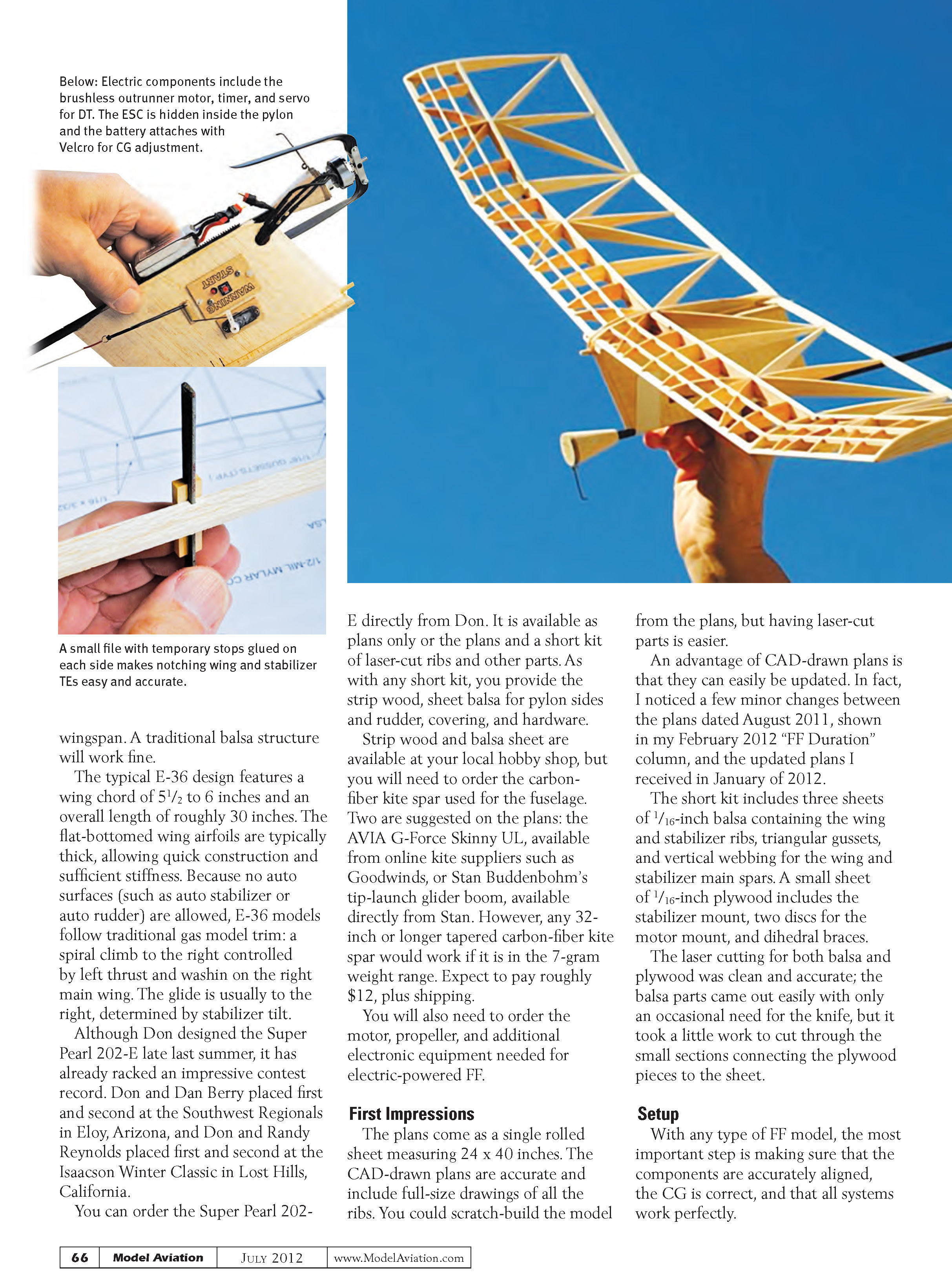
The short kit includes three sheets of 1/16-inch balsa containing the wing and stabilizer ribs, triangular gussets, and vertical webbing for the wing and stabilizer main spars. A small sheet of 1/16-inch plywood includes the stabilizer mount, two discs for the motor mount, and dihedral braces.
The laser cutting for both balsa and plywood was clean and accurate; the balsa parts came out easily with only an occasional need for a knife, but it took a little work to cut through the small sections connecting the plywood pieces to the sheet.
Setup
With any FF model, the most important steps are making sure components are accurately aligned, the CG is correct, and that all systems work perfectly.
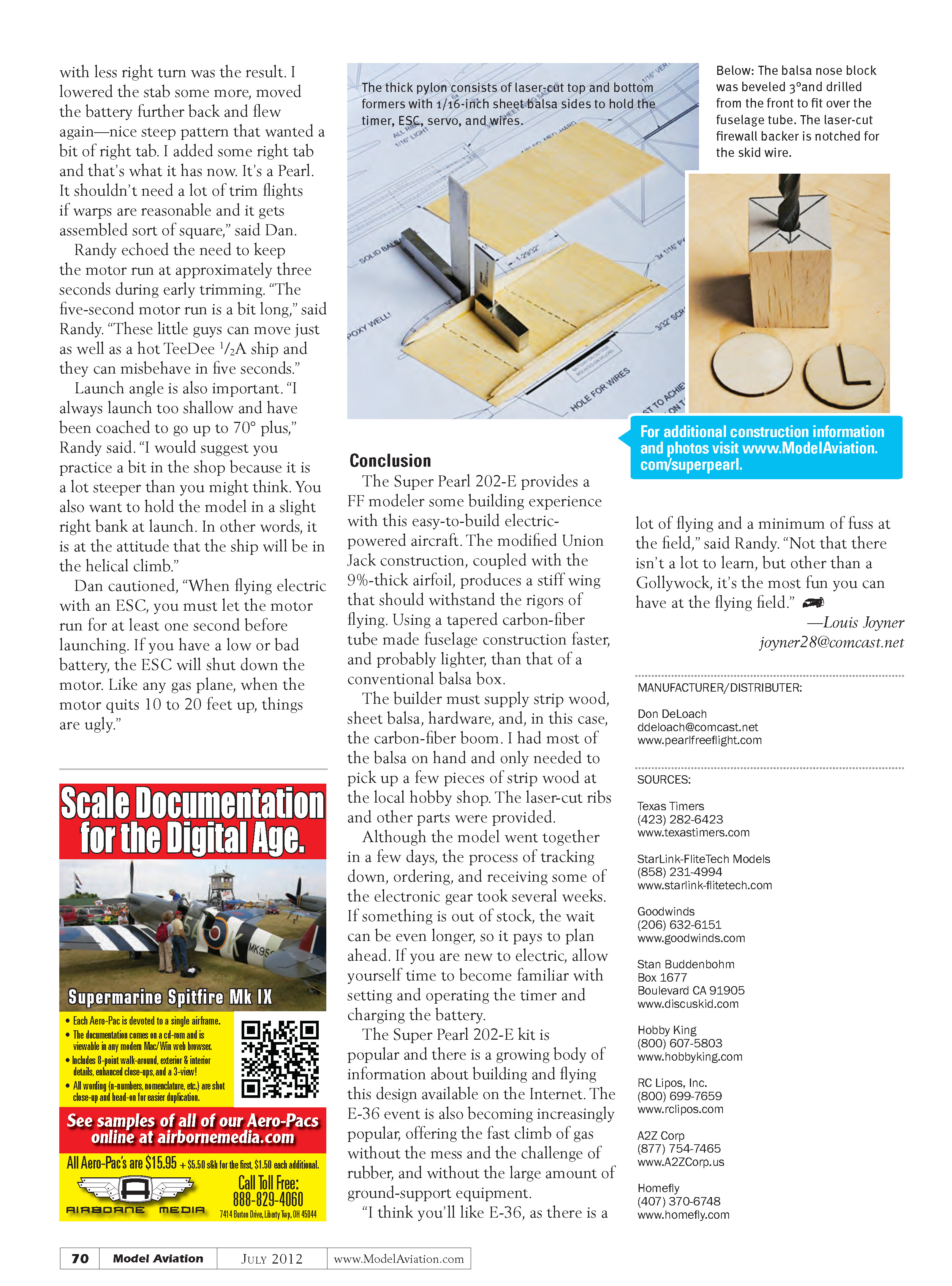
I began by installing the motor and propeller, and fitting the ESC, timer, and servo in the pylon. I temporarily taped the pylon and battery in place and attached the wing and stabilizer.
By moving the pylon and battery back and forth along the fuselage, I was able to get the CG exactly as shown on the plans. Then I epoxied the pylon to the fuselage, making sure the pylon and vertical stabilizer were aligned. Setting the pylon upside down made this easy.
Next, I strapped the wing in place and checked the alignment by measuring from the rear of the fuselage to both wingtips, making adjustments until both measurements were equal. On Dan Berry's recommendation, I added 1/16 x 1/4-inch basswood keys to the underside of the leading and trailing edges, tight against the wing mount. The keys ensure the wing is on straight for each flight.
The tightly stretched wing hold-down rubber bands slightly pulled the trailing edge down. I fixed this by adding 3/32-inch thick balsa strips to the top of the wing saddle in the front and rear. I sanded them to match the underside center of the wing, giving full support.
At the back end, I cut out the rudder tab and attached it with two pieces of copper wire to allow adjustment. The 14-gauge wire was too thick to adjust easily and impossible to remove without breaking the tab.
After patching the vertical stabilizer, I cut a piece of 1/16-inch balsa the same size as the tab, sanded it to a wedge shape, and glued it to the right rear of the vertical stabilizer. Movable rudder tabs are too easily knocked out of position and too tempting to tweak.
For DT I added a wire-and-brass-tube lever on the side of the pylon behind the timer. The long arm runs forward, where it is trapped underneath the servo lever. The other end holds a rubber band attached to the front end of the monofilament DT line that runs back to the stabilizer.
I practiced setting the timer, checking motor run and DT times, and ensuring that everything worked.
Flying
If you have experience flying a gas model, the process of testing and flying the Super Pearl 202-E will be familiar. As with any locked-up, pylon-type power model (gas or electric), adjusting the model to fly safely and to its maximum potential involves carefully balancing controls so it flies itself, free of any control from the ground.
Some adjustments, such as side- or downthrust, CG location, and stabilizer tilt, are more effective at low speed and become less effective at higher speeds. Rudder offset, wing washin, and decalage are more effective at high speeds and less effective at low speeds.
On the Super Pearl 202-E, the left-thrust offset helps prevent the model from hooking to the right on launch. Once airspeed builds, the right rudder tab produces the right turn in the climb, while the washin on the right main wing panel produces the left roll needed to balance the right turn, giving the desired corkscrew climb.
Decalage controls the climb angle. Too much decalage and the model will loop; too little and the climb will be flat. For a model without an auto stabilizer, such as the 202-E, the climb angle must be optimized by changing the decalage. This is easy on this model thanks to the adjustment screw on the stabilizer.
Short motor-run flights with the DT set a few seconds after the motor stops allow climb adjustments to be made safely. Gradually lengthen the motor run with repeated test flights until the climb and recovery are right, then optimize the glide.
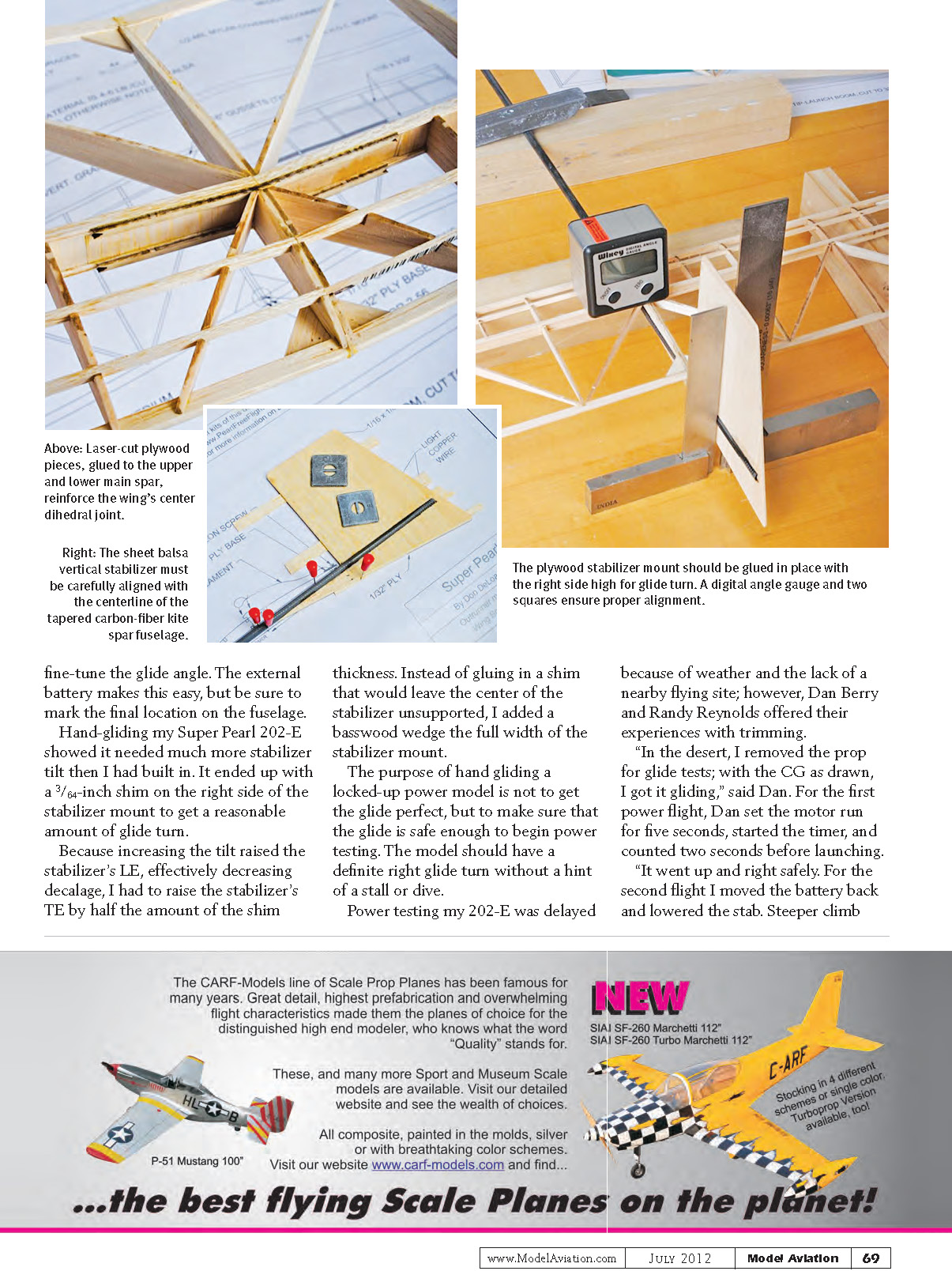
In the glide, the right stabilizer tilt becomes more effective and is used to adjust the diameter of the glide circle. Slight CG adjustments fine-tune the glide angle. The external battery makes this easy, but be sure to mark the final location on the fuselage.
Hand-gliding my Super Pearl 202-E showed it needed much more stabilizer tilt than I had built in. It ended up with a 3/64-inch shim on the right side of the stabilizer mount to get a reasonable amount of glide turn.
Because increasing the tilt raised the stabilizer's leading edge, effectively decreasing decalage, I had to raise the stabilizer's trailing edge by half the amount of the shim thickness. Instead of gluing in a shim that would leave the center of the stabilizer unsupported, I added a basswood wedge the full width of the stabilizer mount.
The purpose of hand-gliding a locked-up power model is not to get the glide perfect, but to make sure that the glide is safe enough to begin power testing. The model should have a definite right glide turn without a hint of a stall or dive.
Power testing my 202-E was delayed because of weather and the lack of a nearby flying site; however, Dan Berry and Randy Reynolds offered their experiences with trimming.
"In the desert, I removed the prop for glide tests; with the CG as drawn, I got it gliding," said Dan. For the first power flight, Dan set the motor run for five seconds, started the timer, and counted two seconds before launching.
"It went up and right safely. For the second flight I moved the battery back and lowered the stab. Steeper climb with less right turn was the result. I lowered the stab some more, moved the battery further back and flew again—nice steep pattern that wanted a bit of right tab. I added some right tab and that's what it has now. It's a Pearl. It shouldn't need a lot of trim flights if warps are reasonable and it gets assembled sort of square," said Dan.
Randy echoed the need to keep the motor run at approximately three seconds during early trimming. "The five-second motor run is a bit long," said Randy. "These little guys can move just as well as a hot TeeDee 1/2A ship and they can misbehave in five seconds."
Launch angle is also important. "I always launch too shallow and have been coached to go up to 70° plus," Randy said. "I would suggest you practice a bit in the shop because it is a lot steeper than you might think. You also want to hold the model in a slight right bank at launch. In other words, it is at the attitude that the ship will be in the helical climb."
Dan cautioned, "When flying electric with an ESC, you must let the motor run for at least one second before launching. If you have a low or bad battery, the ESC will shut down the motor. Like any gas plane, when the motor quits 10 to 20 feet up, things are ugly."
Conclusion
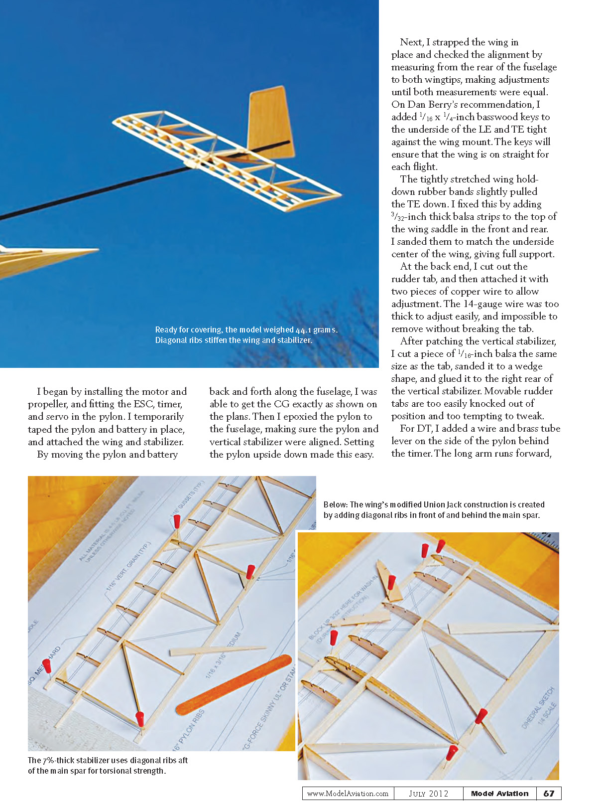
The Super Pearl 202-E provides a FF modeler with building experience on an easy-to-build electric-powered aircraft. The modified Union Jack construction, coupled with the 9%-thick airfoil, produces a stiff wing that should withstand the rigors of flying. Using a tapered carbon-fiber tube made fuselage construction faster, and probably lighter, than that of a conventional balsa box.
The builder must supply strip wood, sheet balsa, hardware, and the carbon-fiber boom. I had most of the balsa on hand and only needed to pick up a few pieces of strip wood at the local hobby shop. The laser-cut ribs and other parts were provided.
Although the model went together in a few days, the process of tracking down, ordering, and receiving some of the electronic gear took several weeks. If something is out of stock, the wait can be even longer, so it pays to plan ahead. If you are new to electric, allow yourself time to become familiar with setting and operating the timer and charging the battery.
The Super Pearl 202-E kit is popular and there is a growing body of information about building and flying this design available on the Internet. The E-36 event is also becoming increasingly popular, offering the fast climb of gas without the mess and the challenge of rubber, and without the large amount of ground-support equipment.
"I think you'll like E-36, as there is a lot of flying and a minimum of fuss at the field," said Randy. "Not that there isn't a lot to learn, but other than a Gollywock, it's the most fun you can have at the flying field."
—Louis Joyner [email protected]
Transcribed from original scans by AI. Minor OCR errors may remain.

