
JR FORZA 700
Charles Anderson — [email protected]
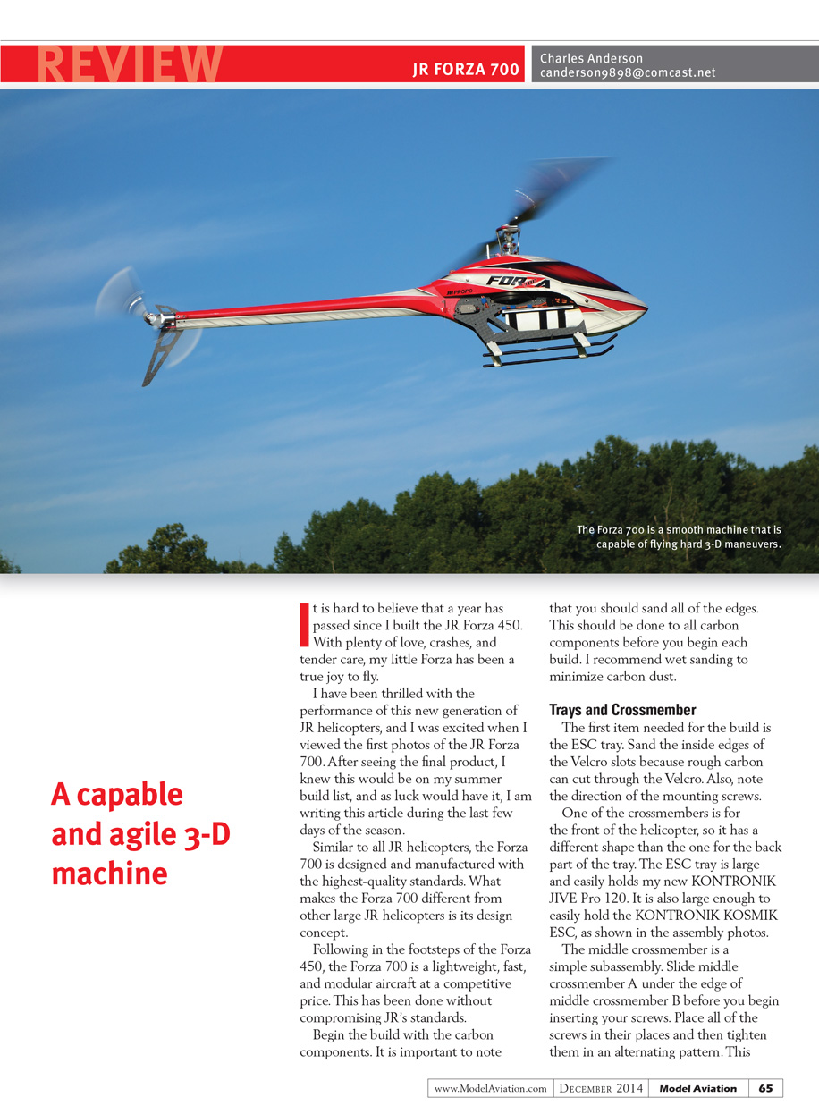
A capable and agile 3-D machine
It is hard to believe that a year has passed since I built the JR Forza 450. With plenty of love, crashes, and tender care, my little Forza has been a true joy to fly.
I have been thrilled with the performance of this new generation of JR helicopters, and I was excited when I viewed the first photos of the JR Forza 700. After seeing the final product, I knew this would be on my summer build list, and as luck would have it, I am writing this article during the last few days of the season.
Similar to all JR helicopters, the Forza 700 is designed and manufactured to the highest-quality standards. What makes the Forza 700 different from other large JR helicopters is its design concept.
Following in the footsteps of the Forza 450, the Forza 700 is a lightweight, fast, and modular aircraft at a competitive price. This has been done without compromising JR's standards.
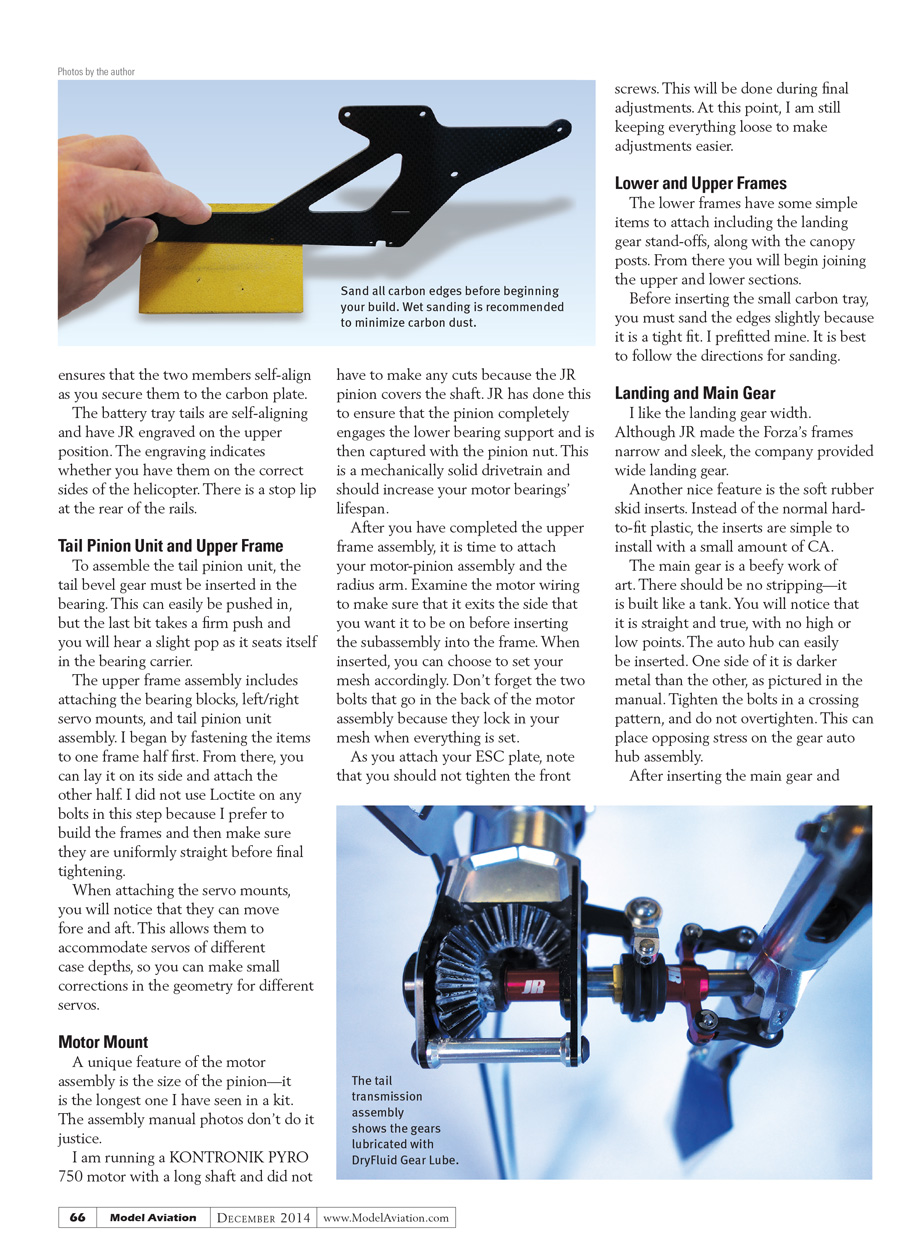
Begin the build with the carbon components. It is important to sand all of the edges. This should be done to all carbon components before you begin each build. I recommend wet sanding to minimize carbon dust.
Trays and Crossmember
The first item needed for the build is the ESC tray. Sand the inside edges of the Velcro slots because rough carbon can cut through the Velcro. Also, note the direction of the mounting screws.
One of the crossmembers is for the front of the helicopter, so it has a different shape than the one for the back part of the tray. The ESC tray is large and easily holds my KONTRONIK JIVE Pro 120. It is also large enough to hold the KONTRONIK KOSMIK ESC, as shown in the assembly photos.
The middle crossmember is a simple subassembly. Slide middle crossmember A under the edge of middle crossmember B before you begin inserting your screws. Place all of the screws in their places and then tighten them in an alternating pattern. This ensures that the two members self-align as you secure them to the carbon plate.
The battery tray tails are self-aligning and have JR engraved on the upper position. The engraving indicates whether you have them on the correct sides of the helicopter. There is a stop lip at the rear of the rails.
Tail Pinion Unit and Upper Frame
To assemble the tail pinion unit, the tail bevel gear must be inserted into the bearing. This can easily be pushed in, but the last bit takes a firm push and you will hear a slight pop as it seats itself in the bearing carrier.
The upper frame assembly includes attaching the bearing blocks, left/right servo mounts, and the tail pinion unit assembly. I began by fastening the items to one frame half first. From there, you can lay it on its side and attach the other half. I did not use Loctite on any bolts in this step because I prefer to build the frames and then make sure they are uniformly straight before final tightening.
When attaching the servo mounts, you will notice that they can move fore and aft. This allows them to accommodate servos of different case depths, so you can make small corrections in the geometry for different servos.
Motor Mount
A unique feature of the motor assembly is the size of the pinion—it is the longest one I have seen in a kit. The assembly manual photos don't do it justice.
I am running a KONTRONIK PYRO 750 motor with a long shaft and did not have to make any cuts because the JR pinion covers the shaft. JR has done this to ensure that the pinion completely engages the lower bearing support and is then captured with the pinion nut. This is a mechanically solid drivetrain and should increase your motor bearings' lifespan.
After you have completed the upper frame assembly, it is time to attach your motor-pinion assembly and the radius arm. Examine the motor wiring to make sure that it exits the side that you want it to be on before inserting the subassembly into the frame. When inserted, you can choose to set your mesh accordingly. Don't forget the two bolts that go in the back of the motor assembly because they lock in your mesh when everything is set.
As you attach your ESC plate, note that you should not tighten the front screws. This will be done during final adjustments. At this point, I kept everything loose to make adjustments easier.
Lower and Upper Frames
The lower frames have some simple items to attach including the landing gear stand-offs and the canopy posts. From there you will begin joining the upper and lower sections.
Before inserting the small carbon tray, you must sand the edges slightly because it is a tight fit. I prefitted mine. It is best to follow the directions for sanding.
Landing and Main Gear
I like the landing gear width. Although JR made the Forza's frames narrow and sleek, the company provided wide landing gear.
Another nice feature is the soft rubber skid inserts. Instead of the normal hard-to-fit plastic, the inserts are simple to install with a small amount of CA.
The main gear is a beefy work of art. There should be no stripping—it is built like a tank. You will notice that it is straight and true, with no high or low points. The auto hub can easily be inserted; one side of it is darker metal than the other, as pictured in the manual. Tighten the bolts in a crossing pattern, and do not overtighten. This can place opposing stress on the gear auto hub assembly.
After inserting the main gear and main shaft, you will set the proper gear mesh. The manual recommends two layers of plastic; I used one of the parts bags, which worked fine. When you insert the lower socket-head bolt that retains the main shaft, it should be snug, but do not over-tighten. This could put additional stress on the gear.
The final part of this assembly is to install the main shaft collar. You should pull upward on the main shaft while tightening the setscrews. JR has included shims in case there is any additional play.
Swash Servo and Swashplate
The Forza 700 servo mounts are adjustable fore and aft to accommodate different servos. When your servos are installed, center your servo horns. If you have not purchased them, I recommend the JR clamping-style servo horns for the Forza 700 kit. They make servo setup and installation a breeze. JR includes a swash alignment tool that slides under the swashplate.
The JR swashplate is a red anodized beauty. Using high-quality bearings, it is as smooth as you might imagine. Ball links and link rods are attached as instructed. The ball links are smooth and do not need any sizing. They are tight to pop on, but when installed, they operate very smoothly.
The center hub lines up as pictured and bolts on with a large shouldered bolt. Make sure this is snug, but do not over-tighten because it will place stress on the materials.
Main Blade and Rotor Head
The washout arm assembly is simple. The main blade holders have preinstalled thrust bearings. One nice feature during this assembly is the smooth main grips that moved freely after installation, which is a sign of proper craftsmanship.
I would not typically discuss rotor head linkages, but my thumbs mentioned it would be a good idea. The linkages from the main grips to the follower arms are tight—and I mean tight—to screw onto the linkage rods. Standard linkage rod tools do not work because the JR plastic is too thick. I worked until my thumbs said "no more" and began using two ball-link pliers to screw the linkage rods together. The plastic is firm and, if you are careful, you can use this method without creating scarring.
Tail
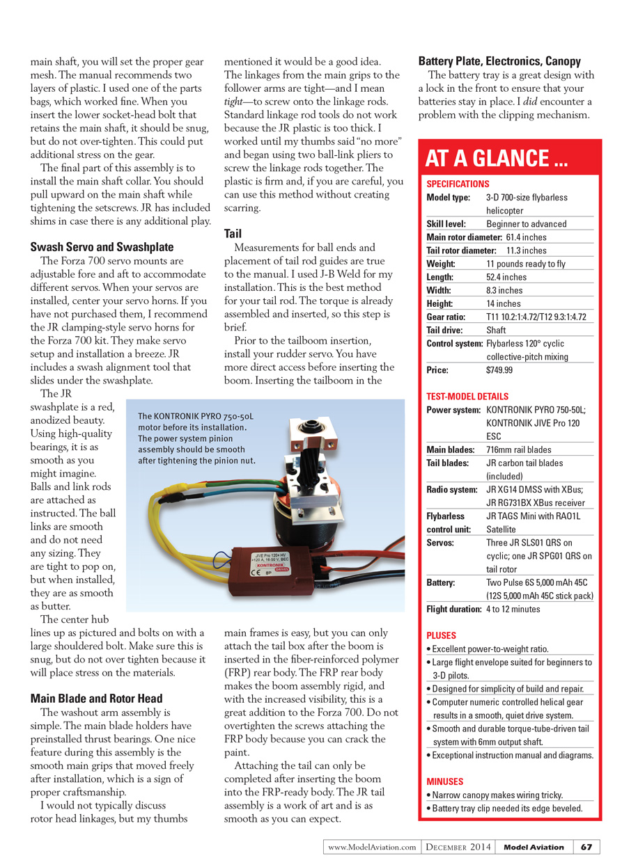
Measurements for ball ends and placement of tail rod guides are true to the manual. I used J-B Weld for my installation. This is the best method for securing your tail rod. The torque tube is already assembled and inserted, so this step is brief.
Prior to the tailboom insertion, install your rudder servo. You have more direct access before inserting the boom. Inserting the tailboom in the main frames is easy, but you can only attach the tail box after the boom is inserted in the fiber-reinforced polymer (FRP) rear body. The FRP rear body makes the boom assembly rigid, and with the increased visibility, this is a great addition to the Forza 700. Do not overtighten the screws attaching the FRP body because you can crack the paint.
Attaching the tail can only be completed after inserting the boom into the FRP rear body. The JR tail assembly is a work of art and is as smooth as you can expect.
Battery Plate, Electronics, Canopy
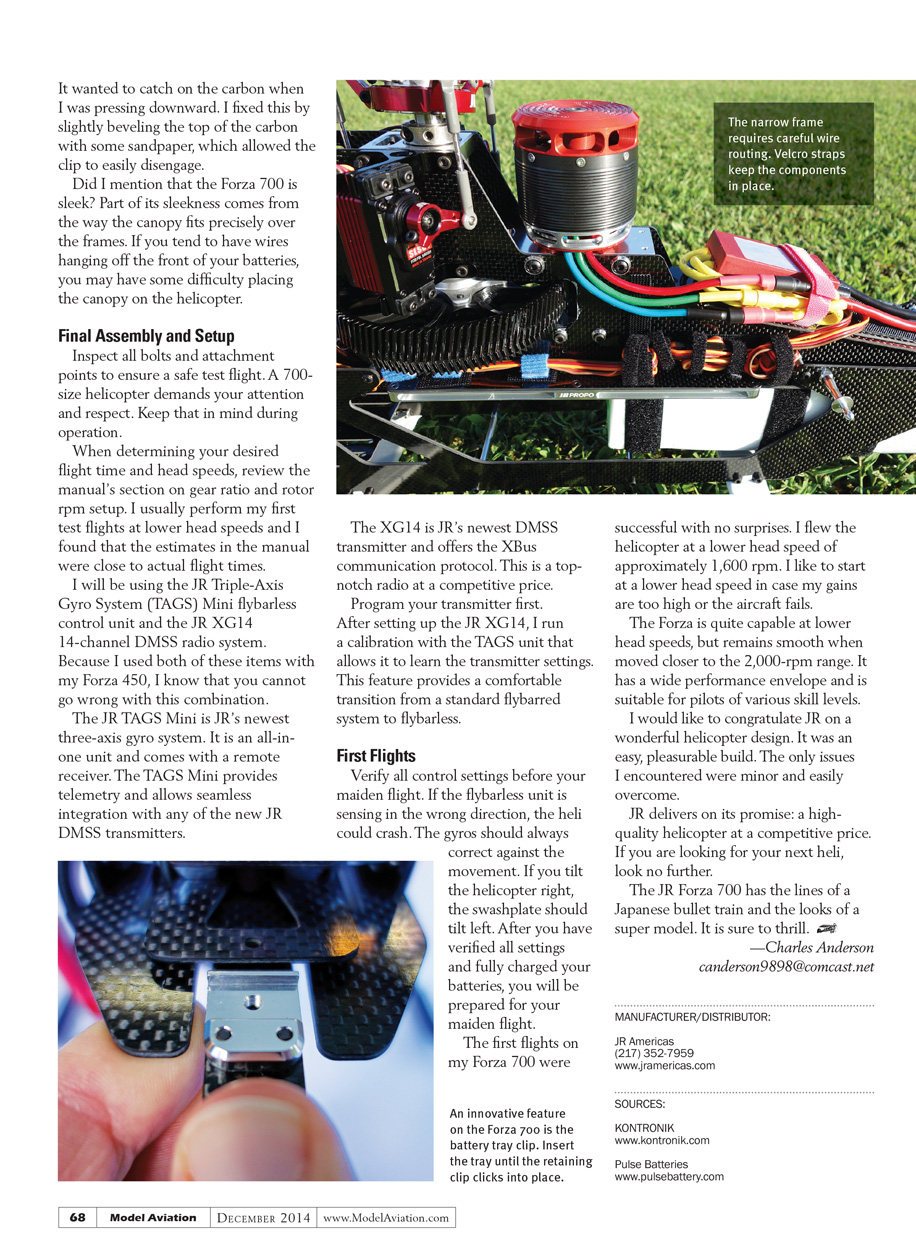
The battery tray is a great design with a lock in the front to ensure that your batteries stay in place. I did encounter a problem with the clipping mechanism: it wanted to catch on the carbon when I was pressing downward. I fixed this by slightly beveling the top of the carbon with some sandpaper, which allowed the clip to easily disengage.
Did I mention that the Forza 700 is sleek? Part of its sleekness comes from the way the canopy fits precisely over the frames. If you tend to have wires hanging off the front of your batteries, you may have some difficulty placing the canopy on the helicopter.
Final Assembly and Setup
Inspect all bolts and attachment points to ensure a safe test flight. A 700-size helicopter demands your attention and respect. Keep that in mind during operation.
When determining your desired flight time and head speeds, review the manual’s section on gear ratio and rotor rpm setup. I usually perform my first test flights at lower head speeds and I found that the estimates in the manual were close to actual flight times.
I used the JR Triple-Axis Gyro System (TAGS) Mini flybarless control unit and the JR XG14 14-channel DMSS radio system. Because I used both of these items with my Forza 450, I know that you cannot go wrong with this combination.
The JR TAGS Mini is JR’s newest three-axis gyro system. It is an all-in-one unit and comes with a remote receiver. The TAGS Mini provides telemetry and allows seamless integration with any of the new JR DMSS transmitters.
The XG14 is JR’s newest DMSS transmitter and offers the XBus communication protocol. This is a top-notch radio at a competitive price.
Program your transmitter first. After setting up the JR XG14, I run a calibration with the TAGS unit that allows it to learn the transmitter settings. This feature provides a comfortable transition from a standard flybarred system to flybarless.
First Flights
Verify all control settings before your maiden flight. If the flybarless unit is sensing in the wrong direction, the heli could crash. The gyros should always correct against the movement. If you tilt the helicopter right, the swashplate should tilt left. After you have verified all settings and fully charged your batteries, you will be prepared for your maiden flight.
The first flights on my Forza 700 were successful with no surprises. I flew the helicopter at a lower head speed of approximately 1,600 rpm. I like to start at a lower head speed in case my gains are too high or the aircraft fails.
The Forza is quite capable at lower head speeds, but remains smooth when moved closer to the 2,000 rpm range. It has a wide performance envelope and is suitable for pilots of various skill levels.
I would like to congratulate JR on a wonderful helicopter design. It was an easy, pleasurable build. The only issues I encountered were minor and easily overcome.
JR delivers on its promise: a high-quality helicopter at a competitive price. If you are looking for your next heli, look no further.
The JR Forza 700 has the lines of a Japanese bullet train and the looks of a supermodel. It is sure to thrill.
—Charles Anderson [email protected]
Manufacturer/Distributor
- JR Americas
- Phone: (217) 352-7959
- Website: www.jramericas.com
Sources
- KONTRONIK — www.kontronik.com
- Pulse Batteries — www.pulsebattery.com
Transcribed from original scans by AI. Minor OCR errors may remain.

