
Review: Great Planes Mr. Mulligan EP ARF
Stan Alexander [email protected]
In the 1930s, air racing was all the rage in the United States and Europe. There were no CAD design systems and most designers learned from the old, and sometimes tough, trial-and-error method.
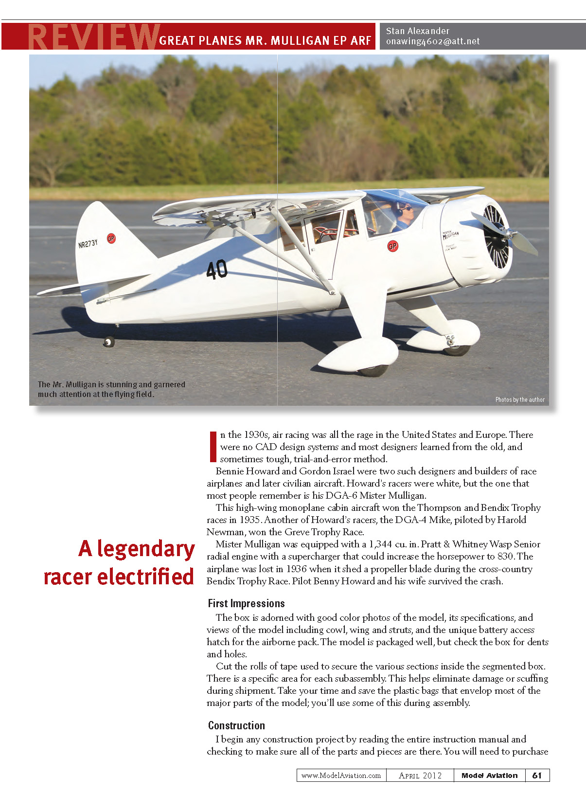
Benny Howard and Gordon Israel were two such designers and builders of race airplanes and later civilian aircraft. Howard’s racers were white, but the one that most people remember is his DGA-6, Mister Mulligan.
This high-wing monoplane cabin aircraft won the Thompson and Bendix Trophy races in 1935. Another of Howard’s racers, the DGA-4 Mike, piloted by Harold Newman, won the Greve Trophy Race.
Mister Mulligan was equipped with a 1,344 cu. in. Pratt & Whitney Wasp Senior radial engine with a supercharger that could increase the horsepower to 830. The airplane was lost in 1936 when it shed a propeller blade during the cross-country Bendix Trophy Race. Pilot Benny Howard and his wife survived the crash.
A legendary racer, electrified
First Impressions
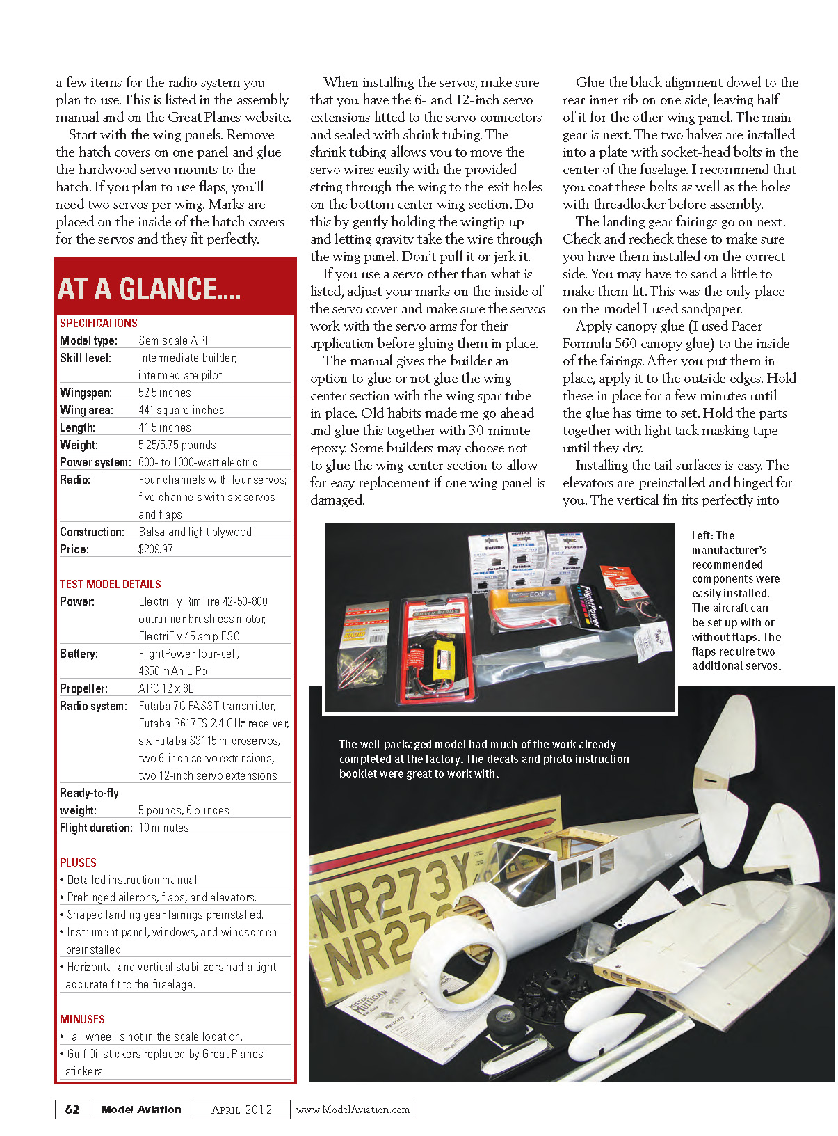
The box is adorned with good color photos of the model, its specifications, and views of the model including cowl, wing and struts, and the unique battery access hatch for the airborne pack. The model is packaged well, but check the box for dents and holes.
Cut the rolls of tape used to secure the various sections inside the segmented box. There is a specific area for each subassembly. This helps eliminate damage or scuffing during shipment. Take your time and save the plastic bags that envelop most of the major parts of the model; you’ll use some of this during assembly.
Construction
I begin any construction project by reading the entire instruction manual and checking to make sure all of the parts and pieces are there. You will need to purchase a few items for the radio system you plan to use. These are listed in the assembly manual and on the Great Planes website.
Start with the wing panels. Remove the hatch covers on one panel and glue the hardwood servo mounts to the hatch. If you plan to use flaps, you'll need two servos per wing. Marks are placed on the inside of the hatch covers for the servos and they fit perfectly.
When installing the servos, make sure that you have the 6- and 12-inch servo extensions fitted to the servo connectors and sealed with shrink tubing. The shrink tubing allows you to move the servo wires easily with the provided string through the wing to the exit holes on the bottom center wing section. Do this by gently holding the wingtip up and letting gravity take the wire through the wing panel. Don't pull it or jerk it.
If you use a servo other than what is listed, adjust your marks on the inside of the servo cover and make sure the servos work with the servo arms for their application before gluing them in place.
The manual gives the builder an option to glue or not glue the wing center section with the wing spar tube in place. Old habits made me go ahead and glue this together with 30-minute epoxy. Some builders may choose not to glue the wing center section to allow for easy replacement if one wing panel is damaged.
Glue the black alignment dowel to the rear inner rib on one side, leaving half of it for the other wing panel. The main gear is next. The two halves are installed into a plate with socket-head bolts in the center of the fuselage. I recommend that you coat these bolts as well as the holes with threadlocker before assembly.
The landing gear fairings go on next. Check and recheck these to make sure you have them installed on the correct side. You may have to sand a little to make them fit. This was the only place on the model I used sandpaper.
Apply canopy glue (I used Pacer Formula 560 canopy glue) to the inside of the fairings. After you put them in place, apply it to the outside edges. Hold these in place for a few minutes until the glue has time to set. Hold the parts together with light tack masking tape until they dry.
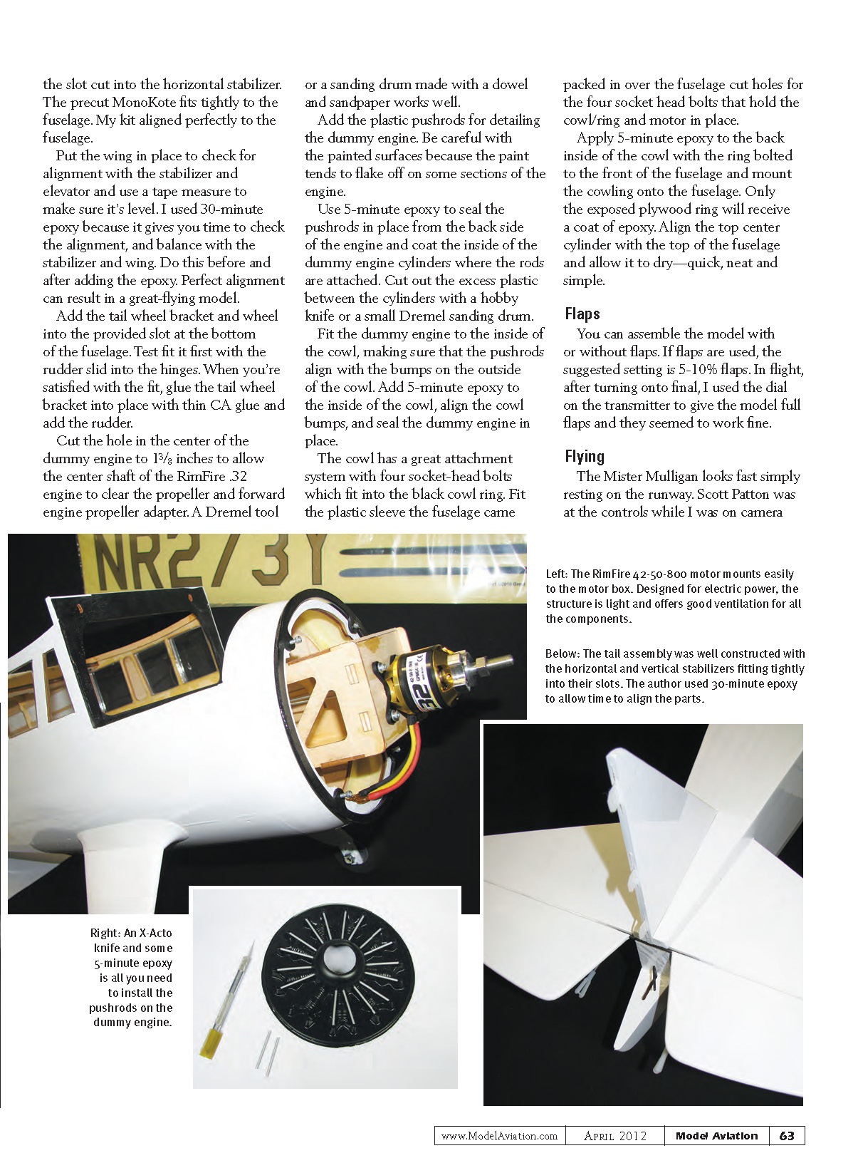
Installing the tail surfaces is easy. The elevators are preinstalled and hinged for you. The vertical fin fits perfectly into the slot cut into the horizontal stabilizer. The precut MonoKote fits tightly to the fuselage. My kit aligned perfectly to the fuselage.
Put the wing in place to check for alignment with the stabilizer and elevator and use a tape measure to make sure it's level. I used 30-minute epoxy because it gives you time to check the alignment and balance with the stabilizer and wing. Do this before and after adding the epoxy. Perfect alignment can result in a great-flying model.
Add the tail wheel bracket and wheel into the provided slot at the bottom of the fuselage. Test fit it first with the rudder slid into the hinges. When you're satisfied with the fit, glue the tail wheel bracket into place with thin CA glue and add the rudder.
Cut the hole in the center of the dummy engine to 1 3/8 inches to allow the center shaft of the RimFire .32 engine to clear the propeller and forward engine propeller adapter. A Dremel tool or a sanding drum made with a dowel and sandpaper works well.
Add the plastic pushrods for detailing the dummy engine. Be careful with the painted surfaces because the paint tends to flake off on some sections of the engine.
Use 5-minute epoxy to seal the pushrods in place from the back side of the engine and coat the inside of the dummy engine cylinders where the rods are attached. Cut out the excess plastic between the cylinders with a hobby knife or a small Dremel sanding drum.
Fit the dummy engine to the inside of the cowl, making sure that the pushrods align with the bumps on the outside of the cowl. Add 5-minute epoxy to the inside of the cowl, align the cowl bumps, and seal the dummy engine in place.
The cowl has a great attachment system with four socket-head bolts which fit into the black cowl ring. Fit the plastic sleeve the fuselage came packed in over the fuselage, and cut holes for the four socket-head bolts that hold the cowl/ring and motor in place.
Apply 5-minute epoxy to the back inside of the cowl with the ring bolted to the front of the fuselage and mount the cowling onto the fuselage. Only the exposed plywood ring will receive a coat of epoxy. Align the top center cylinder with the top of the fuselage and allow it to dry—quick, neat and simple.
Flaps
You can assemble the model with or without flaps. If flaps are used, the suggested setting is 5–10% flaps. In flight, after turning onto final, I used the dial on the transmitter to give the model full flaps and they seemed to work fine.
Flying
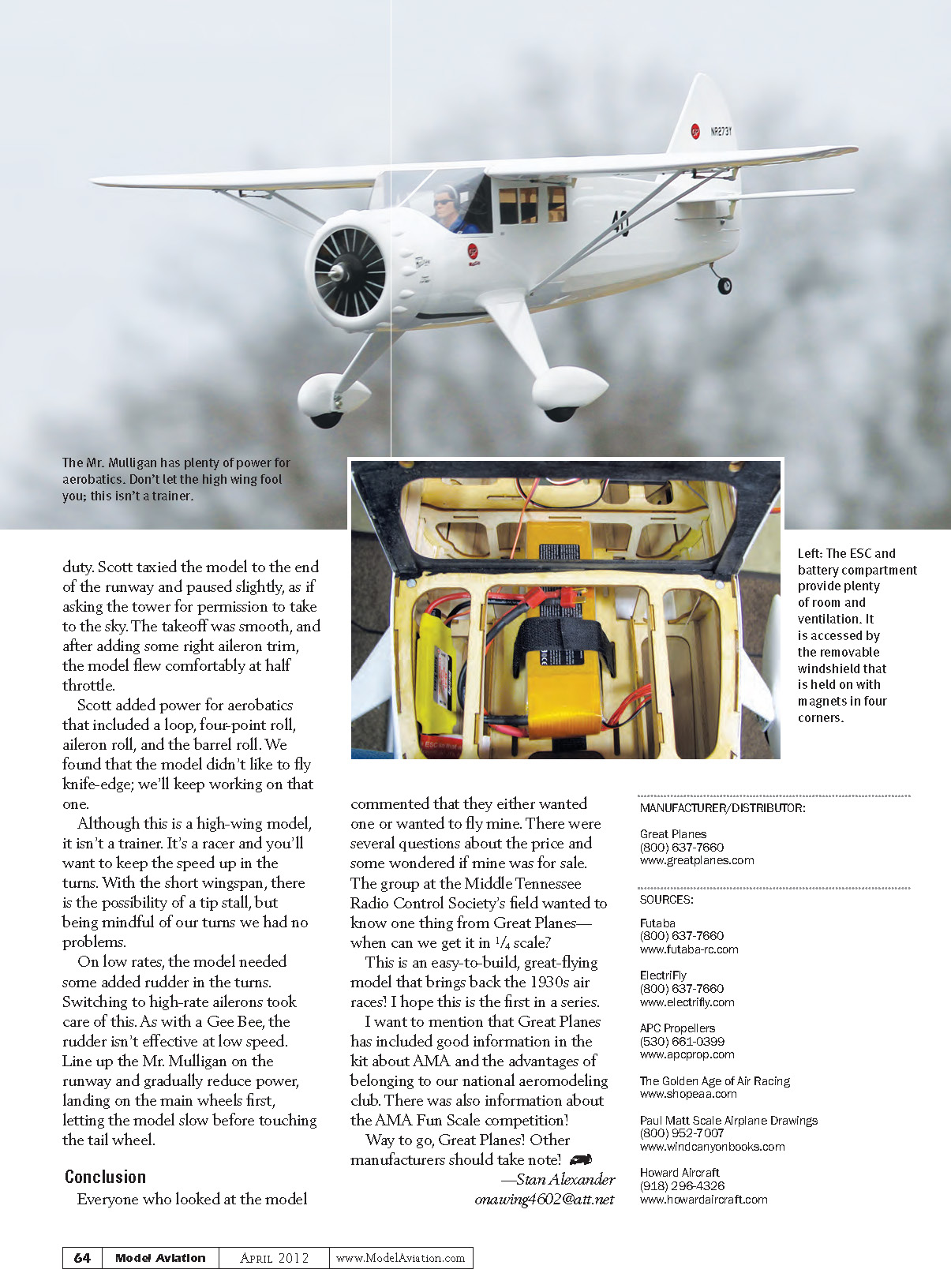
The Mister Mulligan looks fast simply resting on the runway. Scott Patton was at the controls while I was on camera duty. Scott taxied the model to the end of the runway and paused slightly, as if asking the tower for permission to take to the sky. The takeoff was smooth, and after adding some right aileron trim, the model flew comfortably at half throttle.
Scott added power for aerobatics that included a loop, four-point roll, aileron roll, and the barrel roll. We found that the model didn't like to fly knife-edge; we'll keep working on that one.
Although this is a high-wing model, it isn't a trainer. It's a racer and you'll want to keep the speed up in the turns. With the short wingspan, there is the possibility of a tip stall, but being mindful of our turns we had no problems.
On low rates, the model needed some added rudder in the turns. Switching to high-rate ailerons took care of this. As with a Gee Bee, the rudder isn't effective at low speed. Line up the Mr. Mulligan on the runway and gradually reduce power, landing on the main wheels first, letting the model slow before touching the tail wheel.
Conclusion
Everyone who looked at the model commented that they either wanted one or wanted to fly mine. There were several questions about the price and some wondered if mine was for sale. The group at the Middle Tennessee Radio Control Society's field wanted to know one thing from Great Planes—when can we get it in 1/4 scale?
This is an easy-to-build, great-flying model that brings back the 1930s air races! I hope this is the first in a series.
I want to mention that Great Planes has included good information in the kit about AMA and the advantages of belonging to our national aeromodeling club. There was also information about the AMA Fun Scale competition!
Way to go, Great Planes! Other manufacturers should take note!
—Stan Alexander [email protected]
MANUFACTURER/DISTRIBUTOR
- Great Planes
(800) 637-7660 www.greatplanes.com
SOURCES
- Futaba
(800) 637-7660 www.futaba-rc.com
- ElectriFly
(800) 637-7660 www.electrifly.com
- APC Propellers
(530) 661-0399 www.apcprop.com
- The Golden Age of Air Racing
- Paul Matt Scale Airplane Drawings
(800) 952-7007 www.windcanyonbooks.com
- Howard Aircraft
(918) 296-4326 www.howardaircraft.com
Transcribed from original scans by AI. Minor OCR errors may remain.

